
'63 Falcon project

Thread Starter
|
Second Generation Moderator
Feb 2010 ROTM winner
Jan 2013 ROTM winner
Feb 2010 ROTM winner
Jan 2013 ROTM winner
Joined: Aug 2008
Posts: 9,097
From: Portland, Or
ROTM Winner's Club
Yikes! I better be careful what I do; you might pick up some bad habits! 
That frontend is really stout with those braces added, but once it gets boxed in on the bottom it will handle any engine I want to put in there!
That frontend is really stout with those braces added, but once it gets boxed in on the bottom it will handle any engine I want to put in there!
Thread Starter
|
Second Generation Moderator
Feb 2010 ROTM winner
Jan 2013 ROTM winner
Feb 2010 ROTM winner
Jan 2013 ROTM winner
Joined: Aug 2008
Posts: 9,097
From: Portland, Or
ROTM Winner's Club
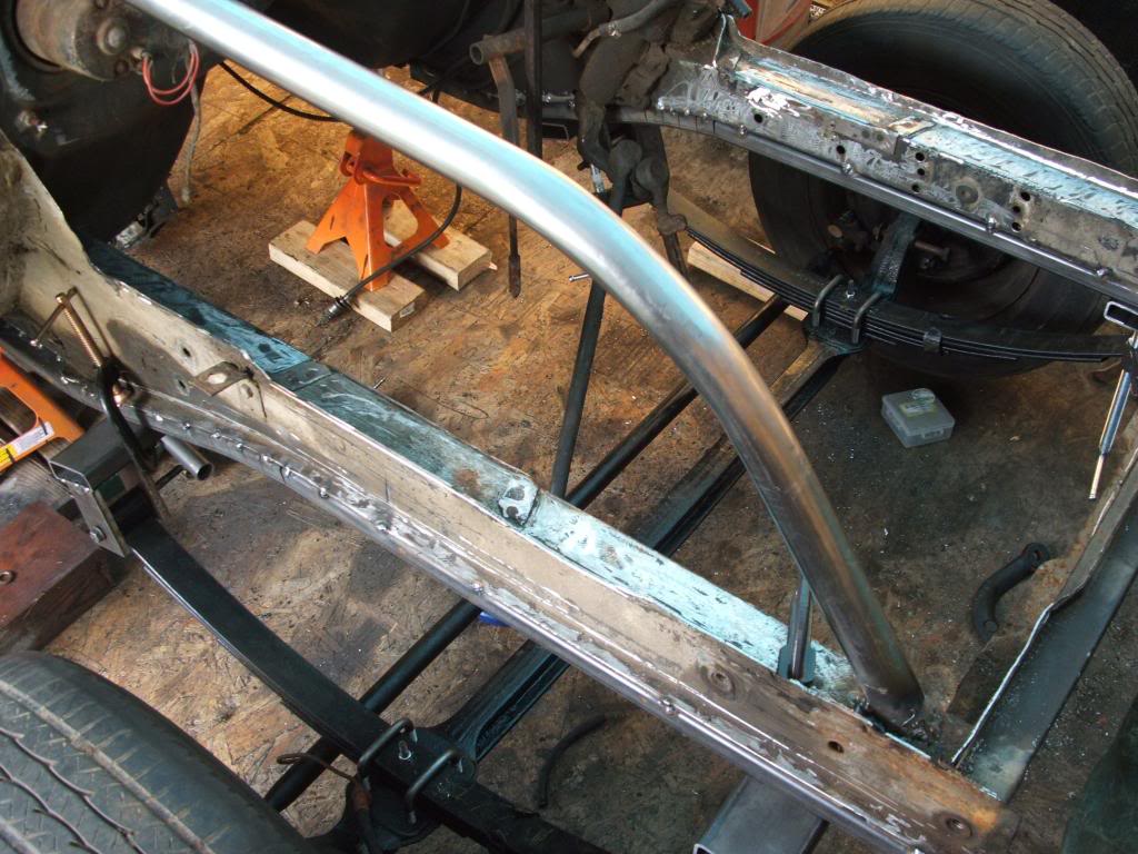
After getting the starter done on the Austin today, I figured I'd put in a few hours on the Falcon. Once everything is set, I'll come back and do a full weld down the frames sides. I cut the 1x3 box tubing and with a straight edge I marked out where I'd need relief cuts to allow it to conform to the frame shape. I made cuts at 1" increments on each side to do the offset bends, and then clamped the tubing to the frame with C clamps. Once it was lined up I tack welded it in place and removed the clamps.
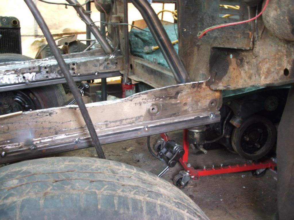
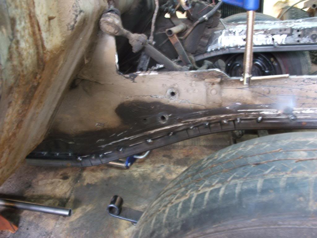
After tacking it I couldn't resist pushing the axle under the frame and seeing where the mounts might end up. I had new spring U bolts bent up this morning, so I bolted the springs on and slid it under. It's much closer than my previous measurements. I thought I'd have to build the mounting points out about 5", but they're only going to be 3", so just a bracket on the side of the frame with gussets should get me where I need to be. Still need to narrow down my kingpin angle, and allow for the rear axle mounting to see how much the angle might change when the rear comes up a touch. If I shoot for 10 degree, I wont lose more than 1-2 degrees when the rear raises, and it should be right in the ballpark still.
I also cut the radiator support off today to get things ready for a full tilt frontend.
Thread Starter
|
Second Generation Moderator
Feb 2010 ROTM winner
Jan 2013 ROTM winner
Feb 2010 ROTM winner
Jan 2013 ROTM winner
Joined: Aug 2008
Posts: 9,097
From: Portland, Or
ROTM Winner's Club
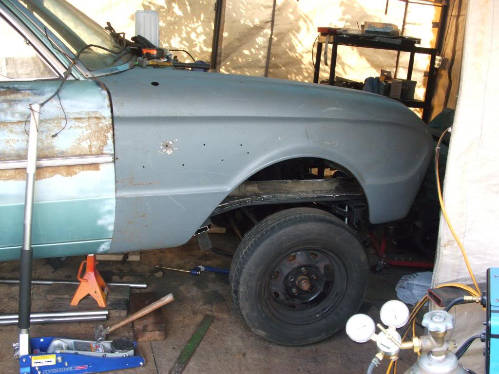
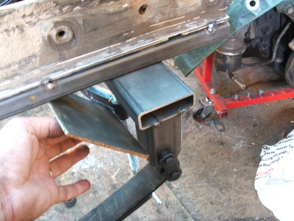
Tacked together some mounts today. Just quick fab and once I have things lined up, and kingpin angle determined, then I'll add gussets and round the corners, etc. I set the front axle 1.5" forward and clamped the mounts. Then I set the fender on to see how it looks. Not too keen on the altered wheelbase look here, so I think I'll move it back more towards stock 109.5" wheelbase. Thought I'd like it moved forward on this car, but thestock location is forward enough that it doesn't need much more. I think just .75" will look better.
Thread Starter
|
Second Generation Moderator
Feb 2010 ROTM winner
Jan 2013 ROTM winner
Feb 2010 ROTM winner
Jan 2013 ROTM winner
Joined: Aug 2008
Posts: 9,097
From: Portland, Or
ROTM Winner's Club
In the next couple days I'm going to build a wood mockup engine, so I can figure out how my headers fit, and what I need to do to the steering box, and anything else that might interfere. I'm going to lay my bellhousing on a piece of cardboard to mark out the holes and shape, then mount the cardboard on the back of the 454 and trace the head shape on it. Then I'll transfer the shape to two pieces of plywood, and cut them out with the jigsaw. After that I'll cut three 2"x6" pieces the length of the engine and screw them between the templates at the exhaust port angle. That should give me the general engine shape, plus allow me to screw the headers to the 2x6's to see if there are any issues with interference. I will mount the third 2x6 on the bottom so it will represent oilpan, and I can set height to clear the oilpan below.
I'd love one of those plastic engines, but they're too spendy to use a couple times.
I'd love one of those plastic engines, but they're too spendy to use a couple times.

Senior Moderator
January 2010 ROTM Winner
January 2010 ROTM Winner
Joined: Oct 2007
Posts: 18,306
From: The 'Burbs of Chicago

Nice work so far. One question though, the way the leaf springs are mounted beyond the frame, what do you have planned to keep the frame from twisting up once there's weight on it?
Thread Starter
|
Second Generation Moderator
Feb 2010 ROTM winner
Jan 2013 ROTM winner
Feb 2010 ROTM winner
Jan 2013 ROTM winner
Joined: Aug 2008
Posts: 9,097
From: Portland, Or
ROTM Winner's Club
The outboard mounting points are running under the frame, plus they will get boxed in on the sides and braced up to the top of the frame, so it will be a pyramid shaped support. I don't see any reason that with the heavy box tubing added below, and the boxing of the supports would allow any frame twisting.
I'm copying another Falcon owner's modifications that have been in service for a couple years with a big block blown Buick, so not just tossing something together andd hoping it works. Plus the front mounts are very close to the front crossmember, which holds the frame, and rear mounts are close to the firewall, and the frame there is twice as tall vertically, so more rigidity there.
I'm copying another Falcon owner's modifications that have been in service for a couple years with a big block blown Buick, so not just tossing something together andd hoping it works. Plus the front mounts are very close to the front crossmember, which holds the frame, and rear mounts are close to the firewall, and the frame there is twice as tall vertically, so more rigidity there.
Senior Moderator
January 2010 ROTM Winner
January 2010 ROTM Winner
Joined: Oct 2007
Posts: 18,306
From: The 'Burbs of Chicago
Because of obvious engine/trans clearance issues, my query was more in reference to the front than back. Due to front engine fitment, maybe it's not possible, but having that front box tubing go across as one piece would give you a more rigid front spring mounting point.
Thread Starter
|
Second Generation Moderator
Feb 2010 ROTM winner
Jan 2013 ROTM winner
Feb 2010 ROTM winner
Jan 2013 ROTM winner
Joined: Aug 2008
Posts: 9,097
From: Portland, Or
ROTM Winner's Club
Doesn't show well in the pictures, but the front crossmember is less than two inches from the front mounts. I think it would be redundant to add another crossmember so close to the existing one.
Senior Moderator
January 2010 ROTM Winner
January 2010 ROTM Winner
Joined: Oct 2007
Posts: 18,306
From: The 'Burbs of Chicago
Maybe it would be redundant, but that car was designed as a uni-body giving the front "frame" it's strength and rigidity. You would know better since you're there though, as to the integrity of that crossmember. I realize you are changing factory design just a tad! It was only a thought.
Thread Starter
|
Second Generation Moderator
Feb 2010 ROTM winner
Jan 2013 ROTM winner
Feb 2010 ROTM winner
Jan 2013 ROTM winner
Joined: Aug 2008
Posts: 9,097
From: Portland, Or
ROTM Winner's Club
Maybe it would be redundant, but that car was designed as a uni-body giving the front "frame" it's strength and rigidity. You would know better since you're there though, as to the integrity of that crossmember. I realize you are changing factory design just a tad! It was only a thought.
I think once everything is braced, boxed, and gussetted, it will handle anything I throw at it.