Installing a LS1 in my 1977 Camaro


#93
 08-19-2011, 06:23 PM

I got some more wiring done. No pics today but did make some progress. If I wanted to do this quick and dirty, I would have had it running by now. Takes longer to try to hide everything. Plus I am still gathering information.
Yesterday I was cruising through the High Tech Retrofits area and came across mwhizard's twin turbo thread. What a fabricator. I read the entire thread. One of the posts caught my attention. Mwhizard had a vacuum line running from his fuel regulator to the manifold. Someone who noticed this mentioned that this would not work well.
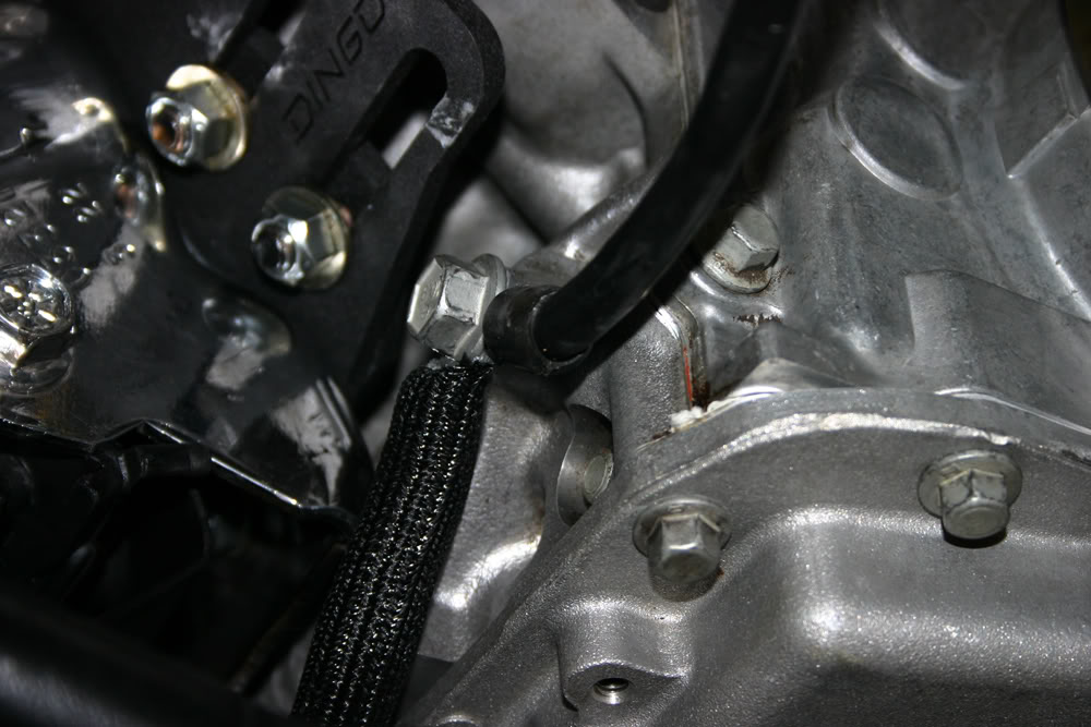
The instructions for installing the EZ-EFI injection on my old small block called for a vacuum line from the regulator to the throttle body. Not knowing any better, I had hooked up the same vacuum line to the intake manifold.
After reading about a potential issue, I forwarded it to my son who is the simulation engineer for the Red Bull NASCAR team. He and I also installed a LS1 in his '79 Camino and he has a 406 small block in his '69 Camaro with a fuel injection system he built from scratch. He knows a little about fuel injection. Because he is in the middle of the season and is traveling so much, he has not seen the car since I got it back from Kooks.
He confirmed that the car would run lean with the vacuum hose hooked up. This is the wording from the post on mwhizard's thread.
Quote:Originally Posted by mrvedit
I notice that you have exactly the same fuel rails, regulator and fuel feed/return layout that I have on my LS2. I was advised not to connect the manifold vacuum line to the regulator, which reduces fuel pressure under high-vacuum cruising and idling. The reason is that the stock ECU is programmed for constant fuel pressure of about 58 lbs at Idle and perhaps 55 lbs at WOT. The vacuum line to the regulator will drop the pressure to about 45 lbs which would run the engine too lean. The ECU can be programmed to compensate for that, but IMO constant fuel pressure is easier to program. Of course, Turbo Charging adds a lot of complexity to the ECU programming.
Reading that post probably saved me a bunch of grief!!!
I also was unsure of how to hook up the computer to my AC system. I had three leads relating to AC on my harness. The harness guy said I needed to talk to Vintage Air. They didn't know which wires were key and were afraid to make a guess because they might be held liable if there was a problem.
Google was the next step. I found LT1 Swap. He has been doing computers for quite awhile on both LT1's and LS motors. Lots of good information here.
I sent him an e-mail to ask if he knew which leads were important. He responded with the two that would do the trick. They are "a/c request" and "a/c clutch status". He said the computer was looking for 12V when the compressor is on. This is the same signal the EZ-EFI looked for so I had already run the wiring. I tapped these two leads into that harness and, hopefully, I should be good to go. I really appreciated this info.
I found a couple of terminal blocks today that I will be using for all of the 12V battery leads I have to hook up. My buddy Reese was over today to check on my progress. We put the car in the air and discussed possiblities for installing the terminal blocks. It looks like I will be putting them on the inside of the frame connectors where they attach to the front subframe. This seemed like a good location to avoid as much exhaust heat as possible. Which means I need longer wires. More soldering to do.
#94
08-20-2011, 01:55 AM
I'm not saying the guy was wrong. But it just strikes me as odd that the computer is looking for 12V. Most things in the digital world work on 0-5v with a no mans land between 1.7v and 3.3v.
I guess my digital electronics class is still lingering in my head.
I guess my digital electronics class is still lingering in my head.
#95
08-20-2011, 10:10 PM
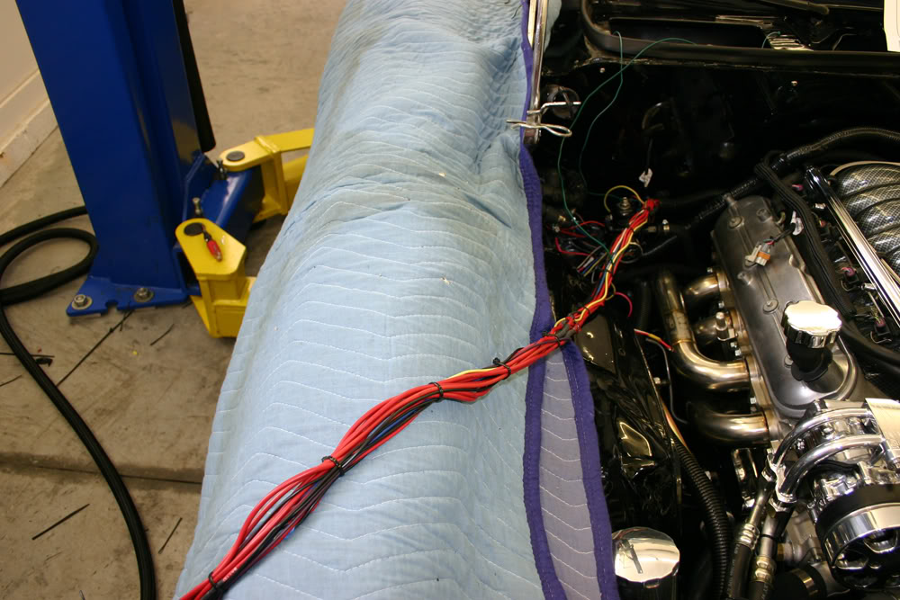
Spent most of the day wiring. Got the relays installed for the fuel pump and for the ECM. To make my wiring for the 12V constant reach to my terminal block, most of my day was taken with soldering on extensions to the wiring so they would reach. This is the harness of wires that will go under the car to various hookups.
I also hooked up my AC wire for the compressor.
The factory dipstick was pretty ugly so I purchased one from Milodon. To install it I needed to remove one of the header bolts to use as a mounting point. When I removed the bolt, I could see that no anti-seize had been applied. So a little time was spent removing all of the bolts, one by one, applying anti-seize and the re-installing them. I was very surprised to find this situation.
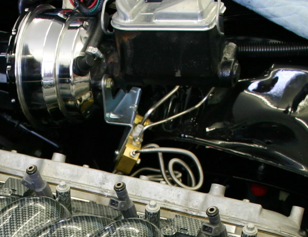
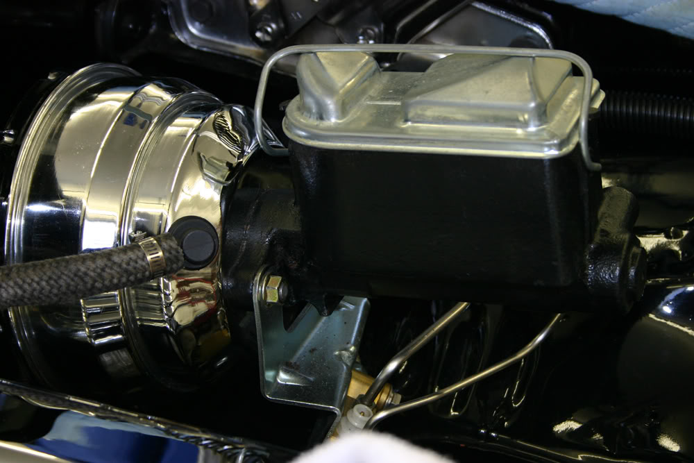
I had also noticed in some of the photos that the paint on the rear part of my master cylinder had been eaten away by brake fluid. I prepped the master cylinder for painting and made it look much better.
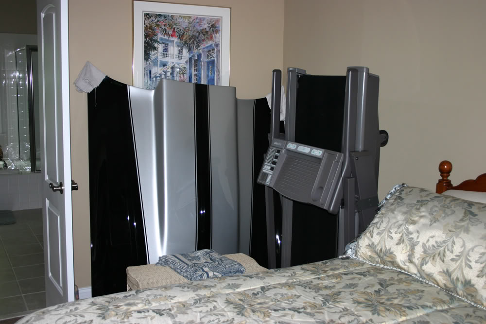
Completing the wiring under the car is the next task. Slowly, but surely, I am getting there. Maybe one day I can remove the hood from my wife's bedroom where it has been safely stashed since April!!!
#97
08-21-2011, 09:31 AM
Join Date: Aug 2008
Location: Portland, Or
Posts: 9,097
Funny how rooms in the houese are referred to as "my wife's", but the garage and shop are always referred to as "my" garage, or shop.  I told my wife she has the whole house, so I get one room in the finished basement, and the garage.
I told my wife she has the whole house, so I get one room in the finished basement, and the garage.
#98
08-22-2011, 05:47 PM
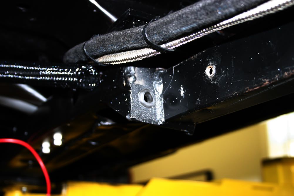
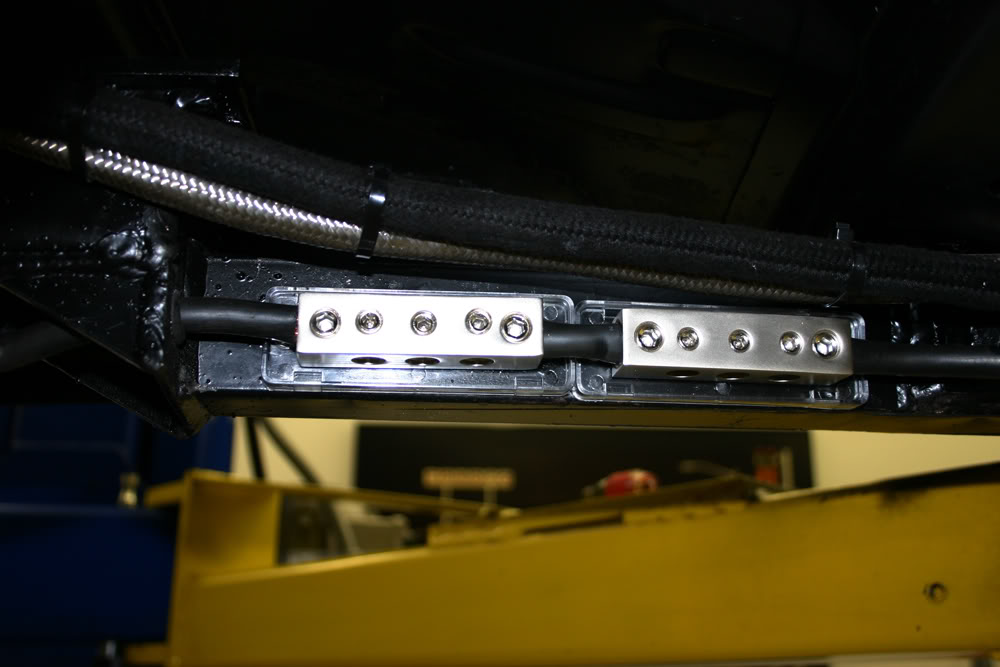
I am getting tired of looking at wiring!!! I finished up everything on the bottom and in the engine compartment today. Since I had so many leads to go to 12V battery and my battery is in my trunk, I decided to come up with a place to mount all of them. The inner side of the frame extenders looked like good place.
Now all I had to do was come up with a terminal block. I looked at the auto parts stores, but they did not have anything that would work. I had to go to Concord to get something and passed a stereo place. A light bulb went on. Sure enough, they had exactly what I was looking for. I bought two of them for about $20 each.
After locating them and making sure everything would fit, I drilled a hole in the end of my frame extender for my main 12V line from the battery to the starter. Next I installed a grommet there.
Then I mounted the two terminal blocks. They were designed to have the main power come in on the ends and were made so that you could connect two them. I then cut my main power line and installed it on the rearmost block. I then cut a small piece of the power wire to connect the two blocks together. After that it was simply a matter of inserting the wire in the hole I had drilled to hook it up to the front block.
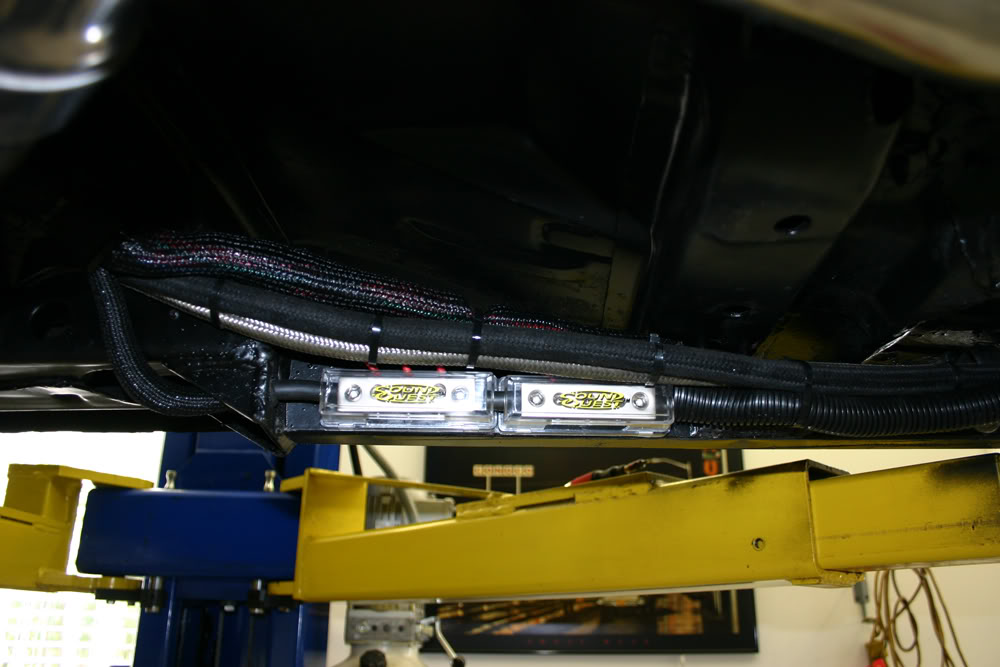
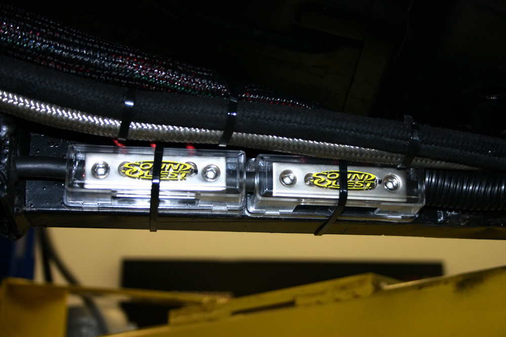
Now it was time to hook up the individual wires. It was pretty simple as the mounting area is open from top to bottom. I simply placed the wires in the holes and cut off whatever extended down. After snugging all the wires, I then ran my wire covers to clean this area up. The blocks also came with covers. They snap on and, to make sure they stay on, I tie wrapped them.
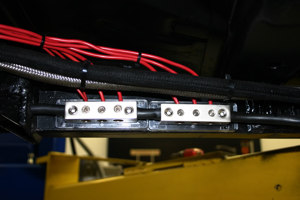
Other wires that were hooked up on the bottom included the speedometer sender wires, the water temp sender for my gauge, the alternator wire, and the fuel pump. I also ran the grounds to a common location on the lower right side of the block.
All I have to hook up now are some wires on the inside for igniton 12V and the wiring to complete my speedometer hookup for the computer and my gauge. Not too much to go. With any luck, I should be able to fire it up tomorrow. Hope that goes well.
I also installed the passenger side coil cover.
#99
08-22-2011, 09:47 PM
Join Date: Aug 2008
Location: Portland, Or
Posts: 9,097
Very slick set up! I never would have thought a stereo place would have terminal splice blocks that beefy. Those covers are really nice!
A lot of electrical distributors carry them, and I've purchased them there. They have some nice ones that accept a couple large cables, and have an assortment of small setscrew terminals for various other size wires.
A lot of electrical distributors carry them, and I've purchased them there. They have some nice ones that accept a couple large cables, and have an assortment of small setscrew terminals for various other size wires.
#100
08-23-2011, 12:42 AM
A word of warning. I have had quite a few distribution blocks, fused and unfused. The clear cover always gets brittle and break/shatter. I think yours will be fine for years because your not driving in the winter and they're not close to heat. I also hang out with a ton of guys with stereos, under the hood is worst followed closely by sitting in direct sunlight in a hatch back. Good looking set up for sure. I just thought I'd share my experience.
I just got a copy of "How to swap an LS motor into anything" I am really wanting to do this. I just need to run my set up first before I can justify spending more on drivetrain.
I just got a copy of "How to swap an LS motor into anything" I am really wanting to do this. I just need to run my set up first before I can justify spending more on drivetrain.