
3.4 to 4.3 TBI VORTEX


Fourth Generation Moderator
October 2009 ROTM
October 2009 ROTM
iTrader: (1)
Joined: Nov 2007
Posts: 10,560
From: Eastern PA,
ROTM Winner's Club
Couple of pics.
Torque arm bolt to the rear that to the tail shaft
Torque arm mount
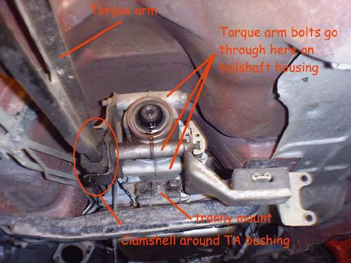
If you are running a Turbo 350 the tail shaft does not have the mount holes and it is not long enough. You will need to make/buy a mount for the arm

Torque arm bolt to the rear that to the tail shaft
Torque arm mount
If you are running a Turbo 350 the tail shaft does not have the mount holes and it is not long enough. You will need to make/buy a mount for the arm
Last edited by Gorn; May 3, 2017 at 10:29 AM.
Fourth Generation Moderator
October 2009 ROTM
October 2009 ROTM
iTrader: (1)
Joined: Nov 2007
Posts: 10,560
From: Eastern PA,
ROTM Winner's Club
To readout th� chip i orderd a universal PROGRAMMER so waiting for it to arrive so i can make a step nu step guide how to read out and program th� content.
Br
Hap
Br
Hap

Thread Starter
|
Newbie
Joined: Apr 2017
Posts: 10
From: Oostende, Belgium
Hi guys, first of al thanks for your support and good comments.
I havent been around much last week, have a lot of stuff going on at work. Looking forward to make the construction from the pictures that Gore sent me (BTW thanks To Gore and MkCoconut for the help)
and lay out the electrical sercuit. Cut off the things i will not need.
So this is pretty much the plan for next friday/saturday
1) make a transaxel member
2) Lay out the wireing
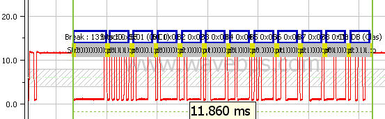
The only thing i am a bit affraid of is, to get the correct map names. It's not so difficult to read out the dump on the chip and to program it by changing the HEX code, but i need to identify the protocols (sentance) that the PCM uses to cumminicatie with each other. As soon as i understand what kind of network protocols are used i can see the identifiers using a Picoscoop i can trace the ifentifiers (words). that way i can change the HEX values (letters).
Here is a Quote from EPROM programming and some basiscs explaining of our Chip:
. I am going to keep this very basic as we do not need to be programming or emulation experts to be able to make very good custom tunes for our cars. The stock EPROM is a 27C25685. The 27 determines the basic type of EPROM which in our case is a 28 DIP or 28 dual in-line pin with two rows of 14 pins each. There are also smaller and larger EPROMS within the 27 series but they do not pertain to us. The C is for ceramic which is the kind of material the EPROM is made of and also plays role in its performance. The 256 stands for the memory capacity of the EPROM and our particular chip is broken up into 32 segments of 8bits each. 85 is the speed of the EPROM in nanoseconds(ns). The ECU requires that the EPROM runs at a certain minimum speed which is about 100ns but I feel it is good to keep them as fast as the stock 85ns or faster. Here is where it gets kinda tricky though. The speed is always defined as 2 digits, so an 85 is 85ns, and a 55 is 55ns, but a 20 is actually 200ns and would be far too slow to be used on our ecus. Just remember to look for something between 85 and 45 and youll be okay.
Now that you have the basic understanding of our EPROM, the next challenge is to understand how the information is written inside of it. The contents of the EPROM are made up entirely of a programming base called hexadecimal or hex for short. This is a 16 digit base that goes as such; 0,1,2,3,4,5,6,7,8,9,A,B,C,D,E,F. After F the numbers start over again with 10,11,12,13,etc. Our normal numbering is called decimal or abbreviated dec for short. So our normal 9dec is equal to 9hex, and 10dec is equal to Ahex. Larger numbers get more complicated such as 16dec is equal to 10hex, and 20dec is equal to 14hex. As you can see it becomes very important to specify what base we are using since the numbers can look very similar but have very different values. I have made up a very basic decimal to hexadecimal conversion chart that will be useful to you. Look for the file Dec to Hex Chart.xls. Very large numbers like FFFFhex is equal to 65535dec and being that we do sometimes use numbers as large as this in tuning, a scientific calculator is a wise investment especially if you plan on tuning EPROMs for customers. Windows has a scientific calculator that works pretty good but switching screens all the time is inconvenient.
Everyone knows by now that the 27C256 EPROM is an 8 bit EPROM with 32 sectors. 8 times 32 is 256, hence the name of the EPROM. The information or code inside the EPROM is stacked in a way that certain legs on the EPROM access certain sectors of the code. When you are accessing the information is it normally displayed as raw data in pages of 16 X 16 resolution. That is 16 columns across with 16 rows down (16x16=128), or essentially a page of 128 slots of information. Each slot is better known as an address. So in our ecus EPROM we have 256 of these pages times 128 addresses per page for a total 32768 slots. Also since we normally talk in hex, 32768dec is equal 8000hex. Our EPROMs addresses start at 0, so likewise they end at 7FFF. For example, the address for our Top Speed Limiter is 7FA5. By altering the data at 7FA5 you alter your top speed limiter!
What this guy doe not menthion is when Converting a hex code it is important to know how many bits is is so if we have a 8 bite code then 2^3, 2^2,2^1, 2^0 is the way to convert the value. So if the code is 1011 the it is 8+0+2+1 this ads up to value 11 dec or A hex. that is the way to convert binary code (on or off; 11V or 2V, 5V or 3V principle )

So if my dashboard does not have to be connected to run, then i dont need to programm it to work with my other new PCM, i can probably get al my signals from else where. After that i need to get rid of the immobeliser. This should not be that hard, as it will be one of the first codes that will be sent to the PCM.
Looking forward to this, my programmer is on its way. Keep you guys posted
BR
Hap
I havent been around much last week, have a lot of stuff going on at work. Looking forward to make the construction from the pictures that Gore sent me (BTW thanks To Gore and MkCoconut for the help)
and lay out the electrical sercuit. Cut off the things i will not need.
So this is pretty much the plan for next friday/saturday
1) make a transaxel member
2) Lay out the wireing
The only thing i am a bit affraid of is, to get the correct map names. It's not so difficult to read out the dump on the chip and to program it by changing the HEX code, but i need to identify the protocols (sentance) that the PCM uses to cumminicatie with each other. As soon as i understand what kind of network protocols are used i can see the identifiers using a Picoscoop i can trace the ifentifiers (words). that way i can change the HEX values (letters).
Here is a Quote from EPROM programming and some basiscs explaining of our Chip:
. I am going to keep this very basic as we do not need to be programming or emulation experts to be able to make very good custom tunes for our cars. The stock EPROM is a 27C25685. The 27 determines the basic type of EPROM which in our case is a 28 DIP or 28 dual in-line pin with two rows of 14 pins each. There are also smaller and larger EPROMS within the 27 series but they do not pertain to us. The C is for ceramic which is the kind of material the EPROM is made of and also plays role in its performance. The 256 stands for the memory capacity of the EPROM and our particular chip is broken up into 32 segments of 8bits each. 85 is the speed of the EPROM in nanoseconds(ns). The ECU requires that the EPROM runs at a certain minimum speed which is about 100ns but I feel it is good to keep them as fast as the stock 85ns or faster. Here is where it gets kinda tricky though. The speed is always defined as 2 digits, so an 85 is 85ns, and a 55 is 55ns, but a 20 is actually 200ns and would be far too slow to be used on our ecus. Just remember to look for something between 85 and 45 and youll be okay.
Now that you have the basic understanding of our EPROM, the next challenge is to understand how the information is written inside of it. The contents of the EPROM are made up entirely of a programming base called hexadecimal or hex for short. This is a 16 digit base that goes as such; 0,1,2,3,4,5,6,7,8,9,A,B,C,D,E,F. After F the numbers start over again with 10,11,12,13,etc. Our normal numbering is called decimal or abbreviated dec for short. So our normal 9dec is equal to 9hex, and 10dec is equal to Ahex. Larger numbers get more complicated such as 16dec is equal to 10hex, and 20dec is equal to 14hex. As you can see it becomes very important to specify what base we are using since the numbers can look very similar but have very different values. I have made up a very basic decimal to hexadecimal conversion chart that will be useful to you. Look for the file Dec to Hex Chart.xls. Very large numbers like FFFFhex is equal to 65535dec and being that we do sometimes use numbers as large as this in tuning, a scientific calculator is a wise investment especially if you plan on tuning EPROMs for customers. Windows has a scientific calculator that works pretty good but switching screens all the time is inconvenient.
Everyone knows by now that the 27C256 EPROM is an 8 bit EPROM with 32 sectors. 8 times 32 is 256, hence the name of the EPROM. The information or code inside the EPROM is stacked in a way that certain legs on the EPROM access certain sectors of the code. When you are accessing the information is it normally displayed as raw data in pages of 16 X 16 resolution. That is 16 columns across with 16 rows down (16x16=128), or essentially a page of 128 slots of information. Each slot is better known as an address. So in our ecus EPROM we have 256 of these pages times 128 addresses per page for a total 32768 slots. Also since we normally talk in hex, 32768dec is equal 8000hex. Our EPROMs addresses start at 0, so likewise they end at 7FFF. For example, the address for our Top Speed Limiter is 7FA5. By altering the data at 7FA5 you alter your top speed limiter!
What this guy doe not menthion is when Converting a hex code it is important to know how many bits is is so if we have a 8 bite code then 2^3, 2^2,2^1, 2^0 is the way to convert the value. So if the code is 1011 the it is 8+0+2+1 this ads up to value 11 dec or A hex. that is the way to convert binary code (on or off; 11V or 2V, 5V or 3V principle )
So if my dashboard does not have to be connected to run, then i dont need to programm it to work with my other new PCM, i can probably get al my signals from else where. After that i need to get rid of the immobeliser. This should not be that hard, as it will be one of the first codes that will be sent to the PCM.
Looking forward to this, my programmer is on its way. Keep you guys posted
BR
Hap
Last edited by HAPLOID; May 7, 2017 at 05:22 AM.
Fourth Generation Moderator
October 2009 ROTM
October 2009 ROTM
iTrader: (1)
Joined: Nov 2007
Posts: 10,560
From: Eastern PA,
ROTM Winner's Club
I have a small history with a hexadecimal editor (Xtree Gold)on PC's. I found that is the program was written in some of the simpler programming languages I could do a lot with it. If the software write in a more complicated software and then compiled it just looked like ascii characters jammed together.
I was talking to our electrical engineer. He said with things like PLC's they would write the code so you could follow the logic with a editor but he said he sees no reason why GM would create a chip without complied code especially when they license the right to sell editing software to tool manufactures.
I am still hoping you can get somewhere with it.
Last edited by Gorn; May 9, 2017 at 06:48 AM.
Thread Starter
|
Newbie
Joined: Apr 2017
Posts: 10
From: Oostende, Belgium
I have a small history with a hexadecimal editor (Xtree Gold)on PC's. I found that is the program was written in some of the simpler programming languages I could do a lot with it. If the software write in a more complicated software and then compiled it just looked like ascii characters jammed together.
I was talking to our electrical engineer. He said with things like PLC's they would write the code so you could follow the logic with a editor but he said he sees no reason why GM would create a chip without complied code especially when they license the right to sell editing software to tool manufactures.
I am still hoping you can get somewhere with it.
I was talking to our electrical engineer. He said with things like PLC's they would write the code so you could follow the logic with a editor but he said he sees no reason why GM would create a chip without complied code especially when they license the right to sell editing software to tool manufactures.
I am still hoping you can get somewhere with it.
AVR studio is also a great compiler but i will not include any Code blocks to write anything in C or C# any other program language to put it on my chip to make it do something. I can see the point and i understand that there are easyer ways of addapting the registers (i understand you), but the software will not let me in to the immobeliser (i think), that is why i desided to get this chip reader. You cannot imagine how much waiting pressure i am experiencing right now.
Lets c if i can make some interesting mods by using this standart Eprom chip. If this chip proves to be very very slow then i may need to change it and get a 32 bit. there for i may need to get all the data off the chip anyway.
Imagine that i can trace all the identifiers of the logical signals send by the ecu to other moduals in the camaro. Then i can basicaly make some more engine mdifications on the standaart chip. I will need to lend a logical signal analyser from a friend of mine.
Last edited by HAPLOID; May 9, 2017 at 01:06 PM.

Thread
Thread Starter
Forum
Replies
Last Post