Car Died While Driving Help Please!!
#1
 03-03-2012, 08:22 AM


I am stuck on the side of the road because the car quit on me while driving and won't fire. it cranks but will not start. it sputters sometimes but won't catch. I have been trying to trace ignition issues detailed on oage 2 of the thread Cold Starts=Stalling or Rough Idle. I can hear the fuel pump running and smell fuel after cranking. Any ideas what to check?
#2
03-03-2012, 11:44 AM

I think craby nailed it in the other thread. Bad wire or connector somewhere in the ignition circuit. You may have a short. I would start from a middle point in the circuit and verify you have good connections/wires there, because then you will know which side your problem is on. If its good there then the issue is after that in the circuit. If not, then its before that point in the circuit.
#3
03-03-2012, 05:22 PM
Right, I have been checking for shorts and such, but the diagram on shoebox's page is wrong. I have a '94 and have been using this diagram:
http://shbox.com/1/95_ign_system_schematic.jpg
My wire paths are different and wire colors are different. Here are my wires:
Coil Connectors
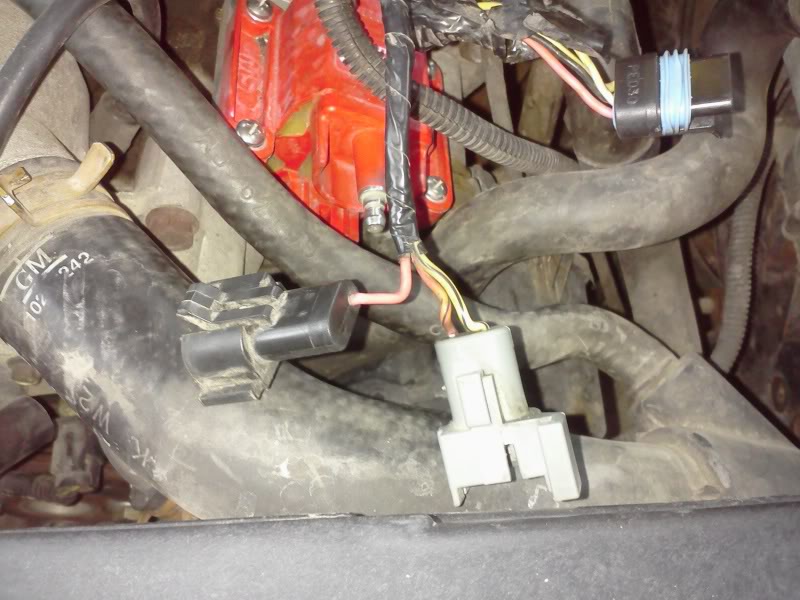
The black connector is the pink +12v from the IGNITION, the grey connector has a pink/black wire that goes to pin A on the ICM, and the yellow/black wire that goes to pin D on the ICM. This is not how the diagram is.
ICM Connectors
I am getting a signal from the PCM to the ICM on pin B, and I have 12v on pin A when testing to ground. The ground circuit is good and I get 12v when testing pin C to +12v, but I get nothing when testing pin D to ground (should be getting 10-12v according to ignition test).
I am going to test the coil and see if maybe it might be bad. I am up for suggestions, and if anyone has a proper diagram for a '94 please let me know.
http://shbox.com/1/95_ign_system_schematic.jpg
My wire paths are different and wire colors are different. Here are my wires:
Coil Connectors
The black connector is the pink +12v from the IGNITION, the grey connector has a pink/black wire that goes to pin A on the ICM, and the yellow/black wire that goes to pin D on the ICM. This is not how the diagram is.
ICM Connectors
I am getting a signal from the PCM to the ICM on pin B, and I have 12v on pin A when testing to ground. The ground circuit is good and I get 12v when testing pin C to +12v, but I get nothing when testing pin D to ground (should be getting 10-12v according to ignition test).
I am going to test the coil and see if maybe it might be bad. I am up for suggestions, and if anyone has a proper diagram for a '94 please let me know.
Last edited by Kubs; 03-03-2012 at 05:26 PM.
#4
03-03-2012, 06:05 PM


Join Date: Mar 2009
Location: Tokeland, Washington
Posts: 21,672
#5
03-03-2012, 06:42 PM
[quote =craby;611061]http://ca maroforums.com/forum/lt1-lt4-tech-9/your-lt1-turns-over-but-will-not-start-65637/[/quote]
That's what i have been following and im saying it is wrong for my model year.
That's what i have been following and im saying it is wrong for my model year.
#9
03-03-2012, 08:55 PM
Between the diagram in your link (which is a '93), my '94, and shoebox's '95, it appears it was changed every year. All 3 are different.
#10
03-03-2012, 09:03 PM
Join Date: Mar 2009
Location: Tokeland, Washington
Posts: 21,672
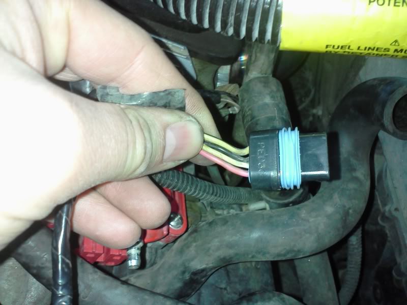
ahh yes the 94 does not have a tach filter. at least i dont think it does. it looks like you have the correct wires and they are the same as a 95. white and black wire and pink and black wire looks faded.