When you click on links to various merchants on this site and make a purchase, this can result in this site earning a commission. Affiliate programs and affiliations include, but are not limited to, the eBay Partner Network.
I have the wiring diagrams and they show which color of wires go to the switches and relays, but I need to know which wire goes to which post. Which publication can I get or does anyone have good pics of your wiring? Thanks!
I'm not sure what your electrical skills are, but this system really requires some knowledge of reading a schematic and understanding how the system works mechanically and electrically. Because the relays and limit switches are used to change the polarity of the headlight doors to open and close, a wire terminated wrongly on a relay or limit switch could connect a positive and a negative wire (ground) which would be a direct short and will weld the contact together. Do you know how to use a meter to check continuity of the relay and switch contacts to find what is the contact common, normally open or normally closed terminals? You also need to understand that the drawing is showing the contact positions when the head light doors are closed. Knowing these two things should allow you to wire the relays and switches as shown in the drawing.
Are you just replacing an existing system's components or is this a complete new installation?
Hi. This is a complete rebuild of an RS/SS that was gutted 20 years ago. As you might suspect I have limited electrical skills but we have got most everything else working. I do know better than to do it wrong. Too many combinations to just start plugging in and see what works or starts smoking. Hoping for some good pics or a very detailed publication I can refer to. I am located an hour south of KCMO if there is an RS I could look at. Thanks for your reply!
Since the relay harness wiring has connector, these pictures may help. Pay attention to the color of the wires in the connector and match to what is shown in the picture. After you're done. I would compare with the drawing as best you can to verify it matches.
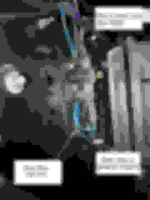
The radiator wall limit switches should look like the pictures below. The first picture is the left door, the second is the right door.
I could not find pictures of outer door limit switches, but I would think they would be wired like the radiator support switches except the brown wire would be substituted for the dark blue wire used on the radiator support switches and what ever color the other wire to the motor is. Again, this is not my preferred method to wire the system, so try to verify by comparing what you've done with the drawing.
Since the relay harness wiring has connector, these pictures may help. Pay attention to the color of the wires in the connector and match to what is shown in the picture. After you're done. I would compare with the drawing as best you can to verify it matches.
The radiator wall limit switches should look like the pictures below. The first picture is the left door, the second is the right door.
I could not find pictures of outer door limit switches, but I would think they would be wired like the radiator support switches except the brown wire would be substituted for the dark blue wire used on the radiator support switches and what ever color the other wire to the motor is. Again, this is not my preferred method to wire the system, so try to verify by comparing what you've done with the drawing.
good evening. This is something like I was looking for. From the pics, I�ll try to match colors to relays and switches. Going to get me closer. I will try to check wire colors to diagram before adding the juice.
The problem with this is these are not my pictures so I can't vouch for the accuracy of how it's wired. I tried to compare the picture with the drawing and from what I could see, they appear to match, but the angle of the photo doesn't show relays #2 and #3 very well.
The problem with this is these are not my pictures so I can't vouch for the accuracy of how it's wired. I tried to compare the picture with the drawing and from what I could see, they appear to match, but the angle of the photo doesn't show relays #2 and #3 very well.
thanks, again. I am going to try to match these up as best as I can. Going to be a couple of days (did I mention this has been quite a long experience so far).
Everett, the docx. document listed is one of the better detailed wiring instructions I've seen to this point. From this information you can pretty much tell which terminals are which. The two terminals at the top of the relay are the power supply for relay coil. The group of three at the bottom are for the relay contacts. The top center terminal would be the contact common and the bottom two terminals of the group would be the open and closed contacts. The normally close contact is the right terminal and the normally open contact is the left terminal.
I saved this document as a pdf. if you're interested.

 07-27-2020, 10:30 AM