
1997 Camaro 3.8 temp issue


Thread Starter
|
Newbie
Joined: Aug 2011
Posts: 4
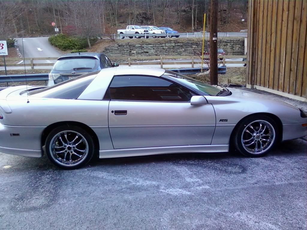
Hello Everyone, I am new here to the forums and I own a 97 Camaro RS 3.8 I have a bout 102,000 miles on it and I have an issue with the temp. Here is the story.
I noticed my fans would never come on no matter how hot the car got. Normally driving around the cars runs around 170-180 on the temp gauge. I wanted to make sure the fans came on if I was in stop and go traffic because when it sits the temp goes up and once I start to drive it would come down again. Needles to say I replaced the Engine Coolant Temp Sensor located right below the intake. In doing so I had to drain the cooling system. So I install the new Coolant Temp Sensor and the fans didnt come on even though the temp went to 240. I unplugged it from the sensor and bot fans worked so I just ran a switch so i could control it manually. Now the fans work but now my car runs over 210 and between 220 normal driving???? This is where I am stumped I bleed the coolant system through the bleeder on the thermostat housing several times but still runs hotter than it used to is there some other bleeder or trick I need to do to get this puppy to run cooler? Please any thoughts are greatly appreciated.
here is a pic of my camaro

Last edited by fire0501; Aug 1, 2011 at 08:44 AM. Reason: adding pic

Newbie
Joined: Apr 2011
Posts: 6
it's some common electrical issue in these cars, i dunno know the specifics, thermal switch, relay somthin or rather you should be throwin a code concerning a fan relay,
real simple fix though bypass the relay and create a manual fan switch that works perfect. ill post some pics of mine in a sec
real simple fix though bypass the relay and create a manual fan switch that works perfect. ill post some pics of mine in a sec
Newbie
Joined: Apr 2011
Posts: 6
holy sheesh, i just remembered that my cars in the body-shop. okay
if you open the hood and go to the fuse box on the drivers side,
and remove the fan relay in the upper left, you have to bridge the connections
between the power and the fan with some wire, try random combos untill a fan
switches on (with keys out of car), then wire in a switch with a ground
then run it into your cab n you're good to go!
remember this is only a temporary fix but it works perfectly, i've been using
this setup for like 5 months.
Last edited by Tweeds; Aug 1, 2011 at 04:53 PM.

Overdrive Member
Joined: Apr 2010
Posts: 3,354
From: Spanaway, WA
210 is the proper operating temp for the 3800 engine. If your gauge stays in that area you are fine. My second fan would not come on unless the temp hit the red or the AC was on. Sounds to me like your car is pretty normal. Now if no fans are comming on then you have an issue with the primary fan. Disconnecting the sensor puts the computer in fail safe mode which will turn on both fans regardless of the temp. This also puts the engine back in open loop or limp home mode which restricts the sensor readings and limits the power the engine can produce.
Massey
Massey
Thread Starter
|
Newbie
Joined: Aug 2011
Posts: 4
Thanks everyone for the replies. I did run the hot Switch for the fans a couple days ago. What turned out to be bad was the Brand New Coolant Temp sensor. It was reading 30 Degrees above what it should have been. I know this because the Thermostat Opens up at 195 and the gauge would read 220 everytime before the thermostat would open I could tell this by the bleeder screw on the thermostat housing nothing would come out until the car hit 220. I installed the old one and there we go the thermostat opens at 195 and my car runs at 180-195 unless I sit in traffic stop and go and that is why I installed the switch. too many junk parts out here nowadays Thanks For all your replies!

Overdrive Member
Joined: Nov 2006
Posts: 4,042
From: IL

Overdrive Member
Joined: Nov 2006
Posts: 4,042
From: IL
So you get no fan codes/check engine light? Turn the fan on manually and verify if the fan motor(s) are still good.
Document ID# 33407
1996 Chevrolet/Geo Camaro
Electric Cooling Fan Diagnosis
Refer to Cooling Fans .
Circuit Description:
Power for the fan motors is supplied through a fusible link at the battery junction block. The cooling fan relays are energized when current flows from the A/P fan fuse through the relay coils to ground through the PCM. The cooling fan relay #1 control circuit is grounded for low speed fans operation. The cooling fan relay #1 control circuit and the cooling fan relay #2 and #3 circuits are both grounded for high speed fans operation.
During low speed fans operation the PCM supplies a ground path for the engine cooling fan relay #1. This closes the engine cooling fan relay #1 contacts, allowing current to flow from the battery junction block through the relay contacts to the left engine cooling fan. During low speed operation, the ground path for the left cooling fan is through the engine cooling fan relay #3 and the right engine cooling fan motor. The result is a series circuit with both cooling fans running at low speed.
During high speed cooling fan operation the PCM supplies a ground path for the engine cooling fan relay #1. The PCM also supplies a ground path for engine cooling fan relay #2 and engine cooling fan relay #3. For high speed cooling fans operation, the PCM will delay control of the cooling fan #2 and #3 relays for 6 seconds. The 6 second delay ensures that the cooling fan electrical load will not exceed the capacity of the system. During high speed fans operation, both the right and the left engine cooling fans are supplied current from the battery junction block and each cooling fan has its own ground path.
Diagnostic Aids
Check for the following conditions:
Poor connection at the PCM, cooling fan relays, or cooling fan motors. Inspect harness connectors for backed out terminals, improper mating, broken locks, improperly formed or damaged terminals, and poor terminal to wire connection.
Damaged harness. Inspect the wiring harness for damage.
Test Description
Number(s) below refer to the step number(s) on the Diagnostic Table.
Stored diagnostic trouble codes may affect engine cooling fans operation. This diagnostic table may lead to improper diagnosis and replacement of good parts if diagnostic trouble codes are present.
Ambient temperature must be greater than 9�C (48�F) before the PCM will enable the cooling fans due to A/C request. The PCM will enable the cooling fans if A/C refrigerant pressure increases regardless of ambient temperature.
This vehicle is equipped with a PCM which utilizes an Electrically Erasable Programmable Read Only Memory (EEPROM). When the PCM is being replaced, the new PCM must be programmed.
Electric Cooling Fan Diagnosis
Step
Action
Value(s)
Yes
No
1
Was the Powertrain On-Board Diagnostic (OBD) System Check performed?
--
Go to Step 2
Go to the A Powertrain On Board Diagnostic (OBD) System Check
2
Are any PCM DTC(s) stored?
--
Diagnose the PCM DTC(s) first. Go to Powertrain Control Module Diagnosis (Powertrain DTCs)
Go to Step 3
3
Ensure that the engine coolant temperature is less than 100�C (212�F).
Turn the A/C OFF.
Engine running.
Observe the cooling fans.
Are the cooling fan(s) running?
--
Go to Step 32
Go to Step 4
4
Command Fan 1 ON using the scan tool output tests function.
Observe the cooling fans.
Are both cooling fans running at low speed?
--
Go to Step 5
Go to Step 8
5
Command Fan 2 ON using the scan tool output tests function.
Wait 6 seconds.
Observe the cooling fans
Are both fans running at high speed?
--
Go to Step 6
Go to Step 58
6
Important:
Ambient temperature must be greater than 9�C (48�F).
Exit scan tool output tests.
Engine running.
Turn the A/C ON.
Are the cooling fans running?
--
Refer to Diagnostic Aids
Go to Step 7
7
View A/C Request on the scan tool.
Does A/C Request on the scan tool display Yes?
--
Go to Step 77
Go to PCM Controlled A/C Circuit Diagnosis
8
Is either cooling fan running?
--
Go to Step 9
Go to Step 16
9
Is the left cooling fan running?
--
Go to Step 10
Go to Step 14
10
Turn OFF the ignition switch.
Disconnect the right engine cooling fan.
Turn ON the ignition switch.
Command Fan 1 ON using the scan tool output tests function.
Observe the cooling fans.
Is the left engine cooling fan running?
--
Go to Step 11
Go to Step 80
11
Remove the series/parallel engine cooling fan relay #3 from the Underhood Electrical Center.
Is the left engine cooling fan running?
--
Go to Step 12
Go to Step 13
12
Locate and repair short to ground in CKT 532. Refer to Repair Procedures in Electrical Diagnosis.
Is action complete?
--
Go to Step 81
--
13
Check CKT 504 for a short to ground.
If a problem is found, repair as necessary. Refer to Repair Procedures in Electrical Diagnosis.
Was a problem found?
--
Go to Step 81
Go to Step 76
14
Turn OFF the ignition switch.
Disconnect the left engine cooling fan.
Turn ON the ignition switch.
Command Fan 1 ON using the scan tool output tests function.
Observe the cooling fans.
Is the right engine cooling fan running?
--
Go to Step 15
Go to Step 79
15
Replace the left engine cooling fan diode. Refer to Cooling Fans in Electrical Diagnosis.
Is action complete?
--
Go to Step 81
--
16
Ignition ON, engine not running.
Remove the low speed engine cooling fan relay #1 from the Underhood Electrical Center.
Probe Underhood Electrical Center cavity D1 with a test light connected to ground.
Is the test light ON?
--
Go to Step 18
Go to Step 17
17
Identify the cause of no battery positive voltage to Underhood Electrical Center cavity D1:
Blown fuse link. If the fuse link is blown, locate and correct short circuit.
Stalled right engine or left engine cooling fan.
Shorted right engine or left engine cooling fan motor windings.
Short to ground in CKT 402, CKT 532, or CKT 504.
Open in CKT 402.
Repair the cause of no battery positive voltage to Underhood Electrical Center cavity D1. Refer to Repair Procedures in Electrical Diagnosis.
Is action complete?
--
Go to Step 81
--
18
Probe Underhood Electrical Center cavity D5 with a test light connected to ground.
Is the test light ON?
--
Go to Step 20
Go to Step 19
19
Identify the cause of no battery positive voltage to Underhood Electrical Center cavity D5:
Blown fuse. If the fuse is blown, locate short circuit.
CKT 1440 shorted to ground.
Shorted low speed engine cooling fan relay #1 coil.
Shorted series/parallel engine cooling fan relay #3 coil.
Shorted high speed engine cooling fan relay #2 coil.
Circuit unrelated to cooling fans. Refer to Fuse Block Details in Electrical Diagnosis.
CKT 1440 open.
Repair cause of no battery positive voltage to Underhood Electrical Center cavity D5. Refer to Repair Procedures in Electrical Diagnosis.
Is action complete?
--
Go to Step 81
--
20
Turn OFF the ignition switch.
Disconnect both cooling fans.
Connect terminals A and B together at both cooling fan connectors using fused jumpers.
Turn ON the ignition switch.
Connect a test light between Underhood Electrical Center cavities D1 and D4.
Is the test light ON?
--
Go to Step 21
Go to Step 27
21
Connect a test light between Underhood Electrical Center cavities D2 and D5.
Turn ON the ignition switch.
Command Fan 1 ON using the scan tool output tests function.
Observe the test light.
Is the test light ON?
--
Go to Step 22
Go to Step 25
22
Turn OFF the ignition switch
Remove the jumpers from the engine cooling fan connectors and reconnect the cooling fans.
Install a fused jumper between Underhood Electrical Center cavities D1 and D4.
Turn ON the ignition switch.
Observe the cooling fans.
Are both cooling fans running?
--
Go to Step 23
Go to Step 24
23
Check for poor low speed engine cooling fan relay #1 connections at the Underhood Electrical Center.
If a problem is found, repair as necessary. Refer to Repair Procedures in Electrical Diagnosis.
Was a problem found?
--
Go to Step 81
Go to Step 37
24
Check for poor connections at the cooling fan motors.
If a problem is found, repair as necessary. Refer to Repair Procedures in Electrical Diagnosis.
Was a problem found?
--
Go to Step 81
Go to Step 63
25
Turn OFF the ignition switch.
Disconnect the PCM blue connector C1.
Install a fused jumper between Underhood Electrical Center cavities D1 and D2.
Turn ON the ignition switch.
Probe PCM harness connector cavity C1-32 with a test light to ground.
Is the test light ON?
--
Go to Step 77
Go to Step 26
26
Locate and repair open in the cooling fan relay #1 control circuit (CKT 335) between the PCM and Underhood Electrical Center cavity D2.
Is action complete?
--
Go to Step 81
--
27
Turn OFF the ignition switch.
Remove the jumpers from the cooling fan connectors.
Reconnect the cooling fans.
Install a fused jumper between Underhood Electrical Center cavities D1 and D4.
Remove the series/parallel engine cooling fan relay #3 from the Underhood Electrical Center.
Probe Underhood Electrical Center cavity J4 with a test light connected to ground.
Is the test light ON?
--
Go to Step 28
Go to Step 31
28
Connect a test light between Underhood Electrical Center cavities J3 and J4.
Is the test light ON?
--
Go to Step 30
Go to Step 29
29
Check for an open in CKT 504 between Underhood Electrical Center cavity J3 and right engine cooling fan terminal B.
If a problem is found, repair as necessary. Refer to Repair Procedures in Electrical Diagnosis.
Was a problem found?
--
Go to Step 81
Go to Step 57
30
Check for a poor connection at Underhood Relay Center cavities J3 or J4.
If a problem is found, repair as necessary. Refer to Repair Procedures in Electrical Diagnosis.
Was a problem found?
--
Go to Step 81
Go to Step 76
31
Check for an open in CKT 409 between Underhood Relay Center cavity D4 and left engine cooling fan harness connector terminal B.
If a problem is found, repair as necessary. Refer to Repair Procedures in Electrical Diagnosis.
Was a problem found?
--
Go to Step 81
Go to Step 56
32
Using scan tool, view A/C Request.
Does the scan tool display Yes?
--
Go to PCM Controlled A/C Circuit Diagnosis
Go to Step 33
33
Are both cooling fan(s) running at low speed?
--
Go to Step 34
Go to Step 40
34
Remove low speed engine cooling fan relay #1 from the Underhood Relay Center.
Are the cooling fans running?
--
Go to Step 35
Go to Step 36
35
Locate and repair short to voltage in CKT 409. Refer to Repair Procedures in Electrical Diagnosis.
Is action complete?
--
Go to Step 81
--
36
Using a test light connected to B+, probe Underhood Relay Center cavity D2.
Is the test light ON?
--
Go to Step 38
Go to Step 37
37
Replace low speed engine cooling fan relay #1.
Is action complete?
--
Go to Step 81
--
38
Turn OFF the ignition switch
Disconnect the blue PCM connector C1.
Probe Underhood Relay Center cavity D2 with a test light connected to B+.
Is the test light ON?
--
Go to Step 39
Go to Step 77
39
Locate and repair short to ground in the cooling fan relay #1 control circuit (CKT 335). Refer to Repair Procedures in Electrical Diagnosis.
Is action complete?
--
Go to Step 81
--
40
Are both cooling fans running at high speed?
--
Go to Step 41
Go to Step 42
41
View A/C Pressure on the scan tool.
Does the scan tool display voltage less than the specified value?
1.2V
Go to Step 77
Go to Step 44
42
Turn OFF the ignition switch.
Disconnect the PCM.
Turn ON the ignition switch.
Observe the cooling fans.
Is the right engine cooling fan running at high speed?
--
Go to Step 43
Go to Step 77
43
Check for a short to ground in the cooling fan #2 and #3 control circuit (CKT 473).
If a problem is found, repair as necessary. Refer to Repair Procedures in Electrical Diagnosis.
Was a problem found?
--
Go to Step 81
Go to Step 52
44
Turn OFF the ignition switch.
Disconnect the A/C refrigerant pressure sensor electrical connector.
Turn ON the ignition switch.
View A/C Pressure on the scan tool.
Does the scan tool display voltage near the specified value?
0V
Go to Step 46
Go to Step 45
45
Probe the A/C refrigerant pressure signal circuit with a J 39200 Digital Multimeter connected to the A/C refrigerant pressure sensor ground.
Does the digital multimeter display voltage near the specified value?
0V
Go to Step 77
Go to Step 51
46
Probe the A/C refrigerant pressure sensor ground with a test light to B+.
Is the test light ON?
--
Go to Step 47
Go to Step 49
47
Probe the A/C refrigerant pressure sensor 5 volt reference circuit B with a J 39200 Digital Multimeter connected to the A/C refrigerant pressure sensor ground.
Does the digital multimeter display voltage near the specified value?
5V
Go to Step 48
Go to Step 50
48
Replace the A/C refrigerant pressure sensor. Refer to On-Vehicle Service in Heater, Ventilation, and Air Conditioning.
Is action complete?
--
Go to Step 81
--
49
Locate and repair open or short to voltage in the A/C refrigerant pressure sensor ground circuit. Refer to Repair Procedures in Electrical Diagnosis.
Is action complete?
--
Go to Step 81
--
50
Locate and repair open or short to ground in the A/C refrigerant pressure sensor 5 volt reference B circuit. Refer to Repair Procedures in Electrical Diagnosis.
Is action complete?
--
Go to Step 81
--
51
Locate and repair short to voltage in the A/C refrigerant pressure signal circuit. Refer to Repair Procedures in Electrical Diagnosis.
Is action complete?
--
Go to Step 81
--
52
Remove the high speed engine cooling fan relay #2 from the Underhood Electrical Center.
Observe the cooling fans.
Is the right engine cooling fan running at high speed?
--
Go to Step 53
Go to Step 70
53
Remove series/parallel engine cooling fan relay #3 from the Underhood Electrical Center.
Is the right engine cooling fan running at high speed?
--
Go to Step 54
Go to Step 55
54
Locate and repair short to B+ in CKT 504. Refer to Repair Procedures in Electrical Diagnosis.
Is action complete?
--
Go to Step 81
--
55
Locate and repair short to B+ in CKT 532. Refer to Repair Procedures in Electrical Diagnosis.
Is action complete?
--
Go to Step 81
--
56
Check for an open in CKT 532 between Underhood Electrical Center cavity J4 and left engine cooling fan terminal A.
If a problem is found, repair as necessary. Refer to Repair Procedures in Electrical Diagnosis.
Was a problem found?
--
Go to Step 81
Go to Step 79
57
Check for an open in CKT 150 between right engine cooling fan terminal A and ground.
If a problem is found, repair as necessary. Refer to Repair Procedures in Electrical Diagnosis.
Was a problem found?
--
Go to Step 81
Go to Step 80
58
Ignition ON, engine not running.
Remove the high speed engine cooling fan relay #2 from the Underhood Electrical Center.
Install a test light between Underhood Electrical Center cavity F2 and B+.
Command Fan 2 ON using the scan tool output controls function.
Wait 6 seconds.
Observe the test light.
Is the test light ON?
--
Go to Step 61
Go to Step 59
59
Remove the series/parallel engine cooling fan relay #3 from the Underhood Electrical Center.
Install a test light between Underhood Electrical Center cavity J2 and B+.
Command Fan 2 ON using the scan tool output controls function.
Wait 6 seconds.
Observe the test light.
Is the test light ON?
--
Go to Step 78
Go to Step 60
60
Turn OFF the ignition switch.
Disconnect the PCM.
Turn ON the ignition switch.
Check the cooling fan relay #2 and #3 control circuit (CKT 473) for an open or a short to voltage between Underhood Electrical Center cavity J2 and the PCM.
If a problem is found, repair as necessary. Refer to Repair Procedures in Electrical Diagnosis.
Was a problem found?
--
Go to Step 81
Go to Step 77
61
Turn OFF the ignition switch
Reinstall high speed engine cooling fan relay #2.
Disconnect both cooling fan electrical connectors.
Turn ON the ignition switch.
Command Fan 2 ON using the scan tool output controls function.
Wait 6 seconds.
Probe terminal B (CKT 504) at the right engine cooling fan connector with a test light to ground.
Is the test light ON?
--
Go to Step 62
Go to Step 64
62
Probe terminal A (CKT 532) at the left engine cooling fan connector with a test light to B+.
Is the test light ON?
--
Go to Step 63
Go to Step 71
63
Identify cause of inoperative cooling fan:
Open right engine cooling fan motor windings.
Open left engine cooling fan motor windings.
Stalled cooling fan(s).
Replace the affected cooling fan motor. Refer to On-Vehicle Service in Cooling and Radiator.
Is action complete?
--
Go to Step 81
--
64
Remove the high speed engine cooling fan relay #2 from the Underhood Electrical Center.
Turn ON the ignition switch.
Probe Underhood Electrical Center cavity F5 with a test light connected to ground.
Is the test light ON?
--
Go to Step 66
Go to Step 65
65
Locate and repair open in the ignition positive voltage circuit to high speed engine cooling fan relay #2. Refer to Repair Procedures in Electrical Diagnosis.
Is action complete?
--
Go to Step 81
--
66
Probe Underhood Electrical Center F4 with a test light connected to ground.
Is the test light ON?
--
Go to Step 68
Go to Step 67
67
Locate and repair open in battery positive voltage circuit to Underhood Electrical Center cavity F4. Refer to Repair Procedures in Electrical Diagnosis.
Is action complete?
--
Go to Step 81
--
68
Check CKT 504 for an open between right engine cooling fan terminal B and Underhood Electrical Center cavity F1.
If a problem is found, repair as necessary. Refer to Repair Procedures in Electrical Diagnosis.
Was a problem found?
--
Go to Step 81
Go to Step 69
69
Check for poor high speed engine cooling fan relay #2 terminal connections at the Underhood Electrical Center.
If a problem is found, repair as necessary. Refer to Repair Procedures in Electrical Diagnosis.
Was a problem found?
--
Go to Step 81
Go to Step 70
70
Replace high speed engine cooling fan relay #2.
Is action complete?
--
Go to Step 81
--
71
Remove the series/parallel cooling #3 fan relay from the Underhood Electrical Center.
Turn ON the ignition switch.
Probe Underhood Electrical Center cavity J5 with a test light connected to ground.
Is the test light ON?
--
Go to Step 73
Go to Step 72
72
Locate and repair open in battery positive voltage circuit to Underhood Electrical Center cavity J5. Refer to Repair Procedures in Electrical Diagnosis.
Is action complete?
--
Go to Step 81
--
73
Probe Underhood Electrical Center cavity J1 with a test light to B+.
Is the test light ON?
--
Go to Step 75
Go to Step 74
74
Locate and repair open in CKT 150 between Underhood Electrical Center cavity J1 and ground. Refer to Repair Procedures in Electrical Diagnosis.
Is action complete?
--
Go to Step 81
--
75
Check for poor series/parallel engine cooling fan relay #3 terminal connections at the Underhood Electrical Center.
If a problem is found, repair as necessary. Refer to Repair Procedures in Electrical Diagnosis.
Was a problem found?
--
Go to Step 81
Go to Step 76
76
Replace the series/parallel engine cooling fan relay #3.
Is action complete?
--
Go to Step 81
--
77
Replace the PCM.
Important:
The replacement PCM must be programmed. Refer to PCM Replacement/Programming .
Is action complete?
--
Go to Step 81
--
78
Repair open in the cooling fan relay #2 and #3 control circuit (CKT 473) to Underhood Electrical Center cavity F2. Refer to Repair Procedures in Electrical Diagnosis.
Is action complete?
--
Go to Step 81
--
79
Replace the left engine cooling fan motor. Refer to On-Vehicle Service in Cooling and Radiator.
Is action complete?
--
Go to Step 81
--
80
Replace the right engine cooling fan motor. Refer to On-Vehicle Service in Cooling and Radiator.
Is action complete?
Go to Step 81
81
Engine coolant less than 100�C (212�F).
Ensure that the A/C is OFF.
Engine running.
Observe the cooling fans.
Are the cooling fans running?
--
Go to Step 32
Go to Step 82
82
Command Fan 1 ON using the scan tool output tests function.
Observe the cooling fans.
Are both cooling fans running at low speed?
--
Go to Step 83
Go to Step 8
83
Command Fan 2 ON using the scan tool output tests function.
Wait 6 seconds.
Observe the cooling fans.
Are both cooling fans running at high speed?
--
System OK
Go to Step 58
Document ID# 33407
1996 Chevrolet/Geo Camaro
Document ID# 33407
1996 Chevrolet/Geo Camaro
Electric Cooling Fan Diagnosis
Refer to Cooling Fans .
Circuit Description:
Power for the fan motors is supplied through a fusible link at the battery junction block. The cooling fan relays are energized when current flows from the A/P fan fuse through the relay coils to ground through the PCM. The cooling fan relay #1 control circuit is grounded for low speed fans operation. The cooling fan relay #1 control circuit and the cooling fan relay #2 and #3 circuits are both grounded for high speed fans operation.
During low speed fans operation the PCM supplies a ground path for the engine cooling fan relay #1. This closes the engine cooling fan relay #1 contacts, allowing current to flow from the battery junction block through the relay contacts to the left engine cooling fan. During low speed operation, the ground path for the left cooling fan is through the engine cooling fan relay #3 and the right engine cooling fan motor. The result is a series circuit with both cooling fans running at low speed.
During high speed cooling fan operation the PCM supplies a ground path for the engine cooling fan relay #1. The PCM also supplies a ground path for engine cooling fan relay #2 and engine cooling fan relay #3. For high speed cooling fans operation, the PCM will delay control of the cooling fan #2 and #3 relays for 6 seconds. The 6 second delay ensures that the cooling fan electrical load will not exceed the capacity of the system. During high speed fans operation, both the right and the left engine cooling fans are supplied current from the battery junction block and each cooling fan has its own ground path.
Diagnostic Aids
Check for the following conditions:
Poor connection at the PCM, cooling fan relays, or cooling fan motors. Inspect harness connectors for backed out terminals, improper mating, broken locks, improperly formed or damaged terminals, and poor terminal to wire connection.
Damaged harness. Inspect the wiring harness for damage.
Test Description
Number(s) below refer to the step number(s) on the Diagnostic Table.
Stored diagnostic trouble codes may affect engine cooling fans operation. This diagnostic table may lead to improper diagnosis and replacement of good parts if diagnostic trouble codes are present.
Ambient temperature must be greater than 9�C (48�F) before the PCM will enable the cooling fans due to A/C request. The PCM will enable the cooling fans if A/C refrigerant pressure increases regardless of ambient temperature.
This vehicle is equipped with a PCM which utilizes an Electrically Erasable Programmable Read Only Memory (EEPROM). When the PCM is being replaced, the new PCM must be programmed.
Electric Cooling Fan Diagnosis
Step
Action
Value(s)
Yes
No
1
Was the Powertrain On-Board Diagnostic (OBD) System Check performed?
--
Go to Step 2
Go to the A Powertrain On Board Diagnostic (OBD) System Check
2
Are any PCM DTC(s) stored?
--
Diagnose the PCM DTC(s) first. Go to Powertrain Control Module Diagnosis (Powertrain DTCs)
Go to Step 3
3
Ensure that the engine coolant temperature is less than 100�C (212�F).
Turn the A/C OFF.
Engine running.
Observe the cooling fans.
Are the cooling fan(s) running?
--
Go to Step 32
Go to Step 4
4
Command Fan 1 ON using the scan tool output tests function.
Observe the cooling fans.
Are both cooling fans running at low speed?
--
Go to Step 5
Go to Step 8
5
Command Fan 2 ON using the scan tool output tests function.
Wait 6 seconds.
Observe the cooling fans
Are both fans running at high speed?
--
Go to Step 6
Go to Step 58
6
Important:
Ambient temperature must be greater than 9�C (48�F).
Exit scan tool output tests.
Engine running.
Turn the A/C ON.
Are the cooling fans running?
--
Refer to Diagnostic Aids
Go to Step 7
7
View A/C Request on the scan tool.
Does A/C Request on the scan tool display Yes?
--
Go to Step 77
Go to PCM Controlled A/C Circuit Diagnosis
8
Is either cooling fan running?
--
Go to Step 9
Go to Step 16
9
Is the left cooling fan running?
--
Go to Step 10
Go to Step 14
10
Turn OFF the ignition switch.
Disconnect the right engine cooling fan.
Turn ON the ignition switch.
Command Fan 1 ON using the scan tool output tests function.
Observe the cooling fans.
Is the left engine cooling fan running?
--
Go to Step 11
Go to Step 80
11
Remove the series/parallel engine cooling fan relay #3 from the Underhood Electrical Center.
Is the left engine cooling fan running?
--
Go to Step 12
Go to Step 13
12
Locate and repair short to ground in CKT 532. Refer to Repair Procedures in Electrical Diagnosis.
Is action complete?
--
Go to Step 81
--
13
Check CKT 504 for a short to ground.
If a problem is found, repair as necessary. Refer to Repair Procedures in Electrical Diagnosis.
Was a problem found?
--
Go to Step 81
Go to Step 76
14
Turn OFF the ignition switch.
Disconnect the left engine cooling fan.
Turn ON the ignition switch.
Command Fan 1 ON using the scan tool output tests function.
Observe the cooling fans.
Is the right engine cooling fan running?
--
Go to Step 15
Go to Step 79
15
Replace the left engine cooling fan diode. Refer to Cooling Fans in Electrical Diagnosis.
Is action complete?
--
Go to Step 81
--
16
Ignition ON, engine not running.
Remove the low speed engine cooling fan relay #1 from the Underhood Electrical Center.
Probe Underhood Electrical Center cavity D1 with a test light connected to ground.
Is the test light ON?
--
Go to Step 18
Go to Step 17
17
Identify the cause of no battery positive voltage to Underhood Electrical Center cavity D1:
Blown fuse link. If the fuse link is blown, locate and correct short circuit.
Stalled right engine or left engine cooling fan.
Shorted right engine or left engine cooling fan motor windings.
Short to ground in CKT 402, CKT 532, or CKT 504.
Open in CKT 402.
Repair the cause of no battery positive voltage to Underhood Electrical Center cavity D1. Refer to Repair Procedures in Electrical Diagnosis.
Is action complete?
--
Go to Step 81
--
18
Probe Underhood Electrical Center cavity D5 with a test light connected to ground.
Is the test light ON?
--
Go to Step 20
Go to Step 19
19
Identify the cause of no battery positive voltage to Underhood Electrical Center cavity D5:
Blown fuse. If the fuse is blown, locate short circuit.
CKT 1440 shorted to ground.
Shorted low speed engine cooling fan relay #1 coil.
Shorted series/parallel engine cooling fan relay #3 coil.
Shorted high speed engine cooling fan relay #2 coil.
Circuit unrelated to cooling fans. Refer to Fuse Block Details in Electrical Diagnosis.
CKT 1440 open.
Repair cause of no battery positive voltage to Underhood Electrical Center cavity D5. Refer to Repair Procedures in Electrical Diagnosis.
Is action complete?
--
Go to Step 81
--
20
Turn OFF the ignition switch.
Disconnect both cooling fans.
Connect terminals A and B together at both cooling fan connectors using fused jumpers.
Turn ON the ignition switch.
Connect a test light between Underhood Electrical Center cavities D1 and D4.
Is the test light ON?
--
Go to Step 21
Go to Step 27
21
Connect a test light between Underhood Electrical Center cavities D2 and D5.
Turn ON the ignition switch.
Command Fan 1 ON using the scan tool output tests function.
Observe the test light.
Is the test light ON?
--
Go to Step 22
Go to Step 25
22
Turn OFF the ignition switch
Remove the jumpers from the engine cooling fan connectors and reconnect the cooling fans.
Install a fused jumper between Underhood Electrical Center cavities D1 and D4.
Turn ON the ignition switch.
Observe the cooling fans.
Are both cooling fans running?
--
Go to Step 23
Go to Step 24
23
Check for poor low speed engine cooling fan relay #1 connections at the Underhood Electrical Center.
If a problem is found, repair as necessary. Refer to Repair Procedures in Electrical Diagnosis.
Was a problem found?
--
Go to Step 81
Go to Step 37
24
Check for poor connections at the cooling fan motors.
If a problem is found, repair as necessary. Refer to Repair Procedures in Electrical Diagnosis.
Was a problem found?
--
Go to Step 81
Go to Step 63
25
Turn OFF the ignition switch.
Disconnect the PCM blue connector C1.
Install a fused jumper between Underhood Electrical Center cavities D1 and D2.
Turn ON the ignition switch.
Probe PCM harness connector cavity C1-32 with a test light to ground.
Is the test light ON?
--
Go to Step 77
Go to Step 26
26
Locate and repair open in the cooling fan relay #1 control circuit (CKT 335) between the PCM and Underhood Electrical Center cavity D2.
Is action complete?
--
Go to Step 81
--
27
Turn OFF the ignition switch.
Remove the jumpers from the cooling fan connectors.
Reconnect the cooling fans.
Install a fused jumper between Underhood Electrical Center cavities D1 and D4.
Remove the series/parallel engine cooling fan relay #3 from the Underhood Electrical Center.
Probe Underhood Electrical Center cavity J4 with a test light connected to ground.
Is the test light ON?
--
Go to Step 28
Go to Step 31
28
Connect a test light between Underhood Electrical Center cavities J3 and J4.
Is the test light ON?
--
Go to Step 30
Go to Step 29
29
Check for an open in CKT 504 between Underhood Electrical Center cavity J3 and right engine cooling fan terminal B.
If a problem is found, repair as necessary. Refer to Repair Procedures in Electrical Diagnosis.
Was a problem found?
--
Go to Step 81
Go to Step 57
30
Check for a poor connection at Underhood Relay Center cavities J3 or J4.
If a problem is found, repair as necessary. Refer to Repair Procedures in Electrical Diagnosis.
Was a problem found?
--
Go to Step 81
Go to Step 76
31
Check for an open in CKT 409 between Underhood Relay Center cavity D4 and left engine cooling fan harness connector terminal B.
If a problem is found, repair as necessary. Refer to Repair Procedures in Electrical Diagnosis.
Was a problem found?
--
Go to Step 81
Go to Step 56
32
Using scan tool, view A/C Request.
Does the scan tool display Yes?
--
Go to PCM Controlled A/C Circuit Diagnosis
Go to Step 33
33
Are both cooling fan(s) running at low speed?
--
Go to Step 34
Go to Step 40
34
Remove low speed engine cooling fan relay #1 from the Underhood Relay Center.
Are the cooling fans running?
--
Go to Step 35
Go to Step 36
35
Locate and repair short to voltage in CKT 409. Refer to Repair Procedures in Electrical Diagnosis.
Is action complete?
--
Go to Step 81
--
36
Using a test light connected to B+, probe Underhood Relay Center cavity D2.
Is the test light ON?
--
Go to Step 38
Go to Step 37
37
Replace low speed engine cooling fan relay #1.
Is action complete?
--
Go to Step 81
--
38
Turn OFF the ignition switch
Disconnect the blue PCM connector C1.
Probe Underhood Relay Center cavity D2 with a test light connected to B+.
Is the test light ON?
--
Go to Step 39
Go to Step 77
39
Locate and repair short to ground in the cooling fan relay #1 control circuit (CKT 335). Refer to Repair Procedures in Electrical Diagnosis.
Is action complete?
--
Go to Step 81
--
40
Are both cooling fans running at high speed?
--
Go to Step 41
Go to Step 42
41
View A/C Pressure on the scan tool.
Does the scan tool display voltage less than the specified value?
1.2V
Go to Step 77
Go to Step 44
42
Turn OFF the ignition switch.
Disconnect the PCM.
Turn ON the ignition switch.
Observe the cooling fans.
Is the right engine cooling fan running at high speed?
--
Go to Step 43
Go to Step 77
43
Check for a short to ground in the cooling fan #2 and #3 control circuit (CKT 473).
If a problem is found, repair as necessary. Refer to Repair Procedures in Electrical Diagnosis.
Was a problem found?
--
Go to Step 81
Go to Step 52
44
Turn OFF the ignition switch.
Disconnect the A/C refrigerant pressure sensor electrical connector.
Turn ON the ignition switch.
View A/C Pressure on the scan tool.
Does the scan tool display voltage near the specified value?
0V
Go to Step 46
Go to Step 45
45
Probe the A/C refrigerant pressure signal circuit with a J 39200 Digital Multimeter connected to the A/C refrigerant pressure sensor ground.
Does the digital multimeter display voltage near the specified value?
0V
Go to Step 77
Go to Step 51
46
Probe the A/C refrigerant pressure sensor ground with a test light to B+.
Is the test light ON?
--
Go to Step 47
Go to Step 49
47
Probe the A/C refrigerant pressure sensor 5 volt reference circuit B with a J 39200 Digital Multimeter connected to the A/C refrigerant pressure sensor ground.
Does the digital multimeter display voltage near the specified value?
5V
Go to Step 48
Go to Step 50
48
Replace the A/C refrigerant pressure sensor. Refer to On-Vehicle Service in Heater, Ventilation, and Air Conditioning.
Is action complete?
--
Go to Step 81
--
49
Locate and repair open or short to voltage in the A/C refrigerant pressure sensor ground circuit. Refer to Repair Procedures in Electrical Diagnosis.
Is action complete?
--
Go to Step 81
--
50
Locate and repair open or short to ground in the A/C refrigerant pressure sensor 5 volt reference B circuit. Refer to Repair Procedures in Electrical Diagnosis.
Is action complete?
--
Go to Step 81
--
51
Locate and repair short to voltage in the A/C refrigerant pressure signal circuit. Refer to Repair Procedures in Electrical Diagnosis.
Is action complete?
--
Go to Step 81
--
52
Remove the high speed engine cooling fan relay #2 from the Underhood Electrical Center.
Observe the cooling fans.
Is the right engine cooling fan running at high speed?
--
Go to Step 53
Go to Step 70
53
Remove series/parallel engine cooling fan relay #3 from the Underhood Electrical Center.
Is the right engine cooling fan running at high speed?
--
Go to Step 54
Go to Step 55
54
Locate and repair short to B+ in CKT 504. Refer to Repair Procedures in Electrical Diagnosis.
Is action complete?
--
Go to Step 81
--
55
Locate and repair short to B+ in CKT 532. Refer to Repair Procedures in Electrical Diagnosis.
Is action complete?
--
Go to Step 81
--
56
Check for an open in CKT 532 between Underhood Electrical Center cavity J4 and left engine cooling fan terminal A.
If a problem is found, repair as necessary. Refer to Repair Procedures in Electrical Diagnosis.
Was a problem found?
--
Go to Step 81
Go to Step 79
57
Check for an open in CKT 150 between right engine cooling fan terminal A and ground.
If a problem is found, repair as necessary. Refer to Repair Procedures in Electrical Diagnosis.
Was a problem found?
--
Go to Step 81
Go to Step 80
58
Ignition ON, engine not running.
Remove the high speed engine cooling fan relay #2 from the Underhood Electrical Center.
Install a test light between Underhood Electrical Center cavity F2 and B+.
Command Fan 2 ON using the scan tool output controls function.
Wait 6 seconds.
Observe the test light.
Is the test light ON?
--
Go to Step 61
Go to Step 59
59
Remove the series/parallel engine cooling fan relay #3 from the Underhood Electrical Center.
Install a test light between Underhood Electrical Center cavity J2 and B+.
Command Fan 2 ON using the scan tool output controls function.
Wait 6 seconds.
Observe the test light.
Is the test light ON?
--
Go to Step 78
Go to Step 60
60
Turn OFF the ignition switch.
Disconnect the PCM.
Turn ON the ignition switch.
Check the cooling fan relay #2 and #3 control circuit (CKT 473) for an open or a short to voltage between Underhood Electrical Center cavity J2 and the PCM.
If a problem is found, repair as necessary. Refer to Repair Procedures in Electrical Diagnosis.
Was a problem found?
--
Go to Step 81
Go to Step 77
61
Turn OFF the ignition switch
Reinstall high speed engine cooling fan relay #2.
Disconnect both cooling fan electrical connectors.
Turn ON the ignition switch.
Command Fan 2 ON using the scan tool output controls function.
Wait 6 seconds.
Probe terminal B (CKT 504) at the right engine cooling fan connector with a test light to ground.
Is the test light ON?
--
Go to Step 62
Go to Step 64
62
Probe terminal A (CKT 532) at the left engine cooling fan connector with a test light to B+.
Is the test light ON?
--
Go to Step 63
Go to Step 71
63
Identify cause of inoperative cooling fan:
Open right engine cooling fan motor windings.
Open left engine cooling fan motor windings.
Stalled cooling fan(s).
Replace the affected cooling fan motor. Refer to On-Vehicle Service in Cooling and Radiator.
Is action complete?
--
Go to Step 81
--
64
Remove the high speed engine cooling fan relay #2 from the Underhood Electrical Center.
Turn ON the ignition switch.
Probe Underhood Electrical Center cavity F5 with a test light connected to ground.
Is the test light ON?
--
Go to Step 66
Go to Step 65
65
Locate and repair open in the ignition positive voltage circuit to high speed engine cooling fan relay #2. Refer to Repair Procedures in Electrical Diagnosis.
Is action complete?
--
Go to Step 81
--
66
Probe Underhood Electrical Center F4 with a test light connected to ground.
Is the test light ON?
--
Go to Step 68
Go to Step 67
67
Locate and repair open in battery positive voltage circuit to Underhood Electrical Center cavity F4. Refer to Repair Procedures in Electrical Diagnosis.
Is action complete?
--
Go to Step 81
--
68
Check CKT 504 for an open between right engine cooling fan terminal B and Underhood Electrical Center cavity F1.
If a problem is found, repair as necessary. Refer to Repair Procedures in Electrical Diagnosis.
Was a problem found?
--
Go to Step 81
Go to Step 69
69
Check for poor high speed engine cooling fan relay #2 terminal connections at the Underhood Electrical Center.
If a problem is found, repair as necessary. Refer to Repair Procedures in Electrical Diagnosis.
Was a problem found?
--
Go to Step 81
Go to Step 70
70
Replace high speed engine cooling fan relay #2.
Is action complete?
--
Go to Step 81
--
71
Remove the series/parallel cooling #3 fan relay from the Underhood Electrical Center.
Turn ON the ignition switch.
Probe Underhood Electrical Center cavity J5 with a test light connected to ground.
Is the test light ON?
--
Go to Step 73
Go to Step 72
72
Locate and repair open in battery positive voltage circuit to Underhood Electrical Center cavity J5. Refer to Repair Procedures in Electrical Diagnosis.
Is action complete?
--
Go to Step 81
--
73
Probe Underhood Electrical Center cavity J1 with a test light to B+.
Is the test light ON?
--
Go to Step 75
Go to Step 74
74
Locate and repair open in CKT 150 between Underhood Electrical Center cavity J1 and ground. Refer to Repair Procedures in Electrical Diagnosis.
Is action complete?
--
Go to Step 81
--
75
Check for poor series/parallel engine cooling fan relay #3 terminal connections at the Underhood Electrical Center.
If a problem is found, repair as necessary. Refer to Repair Procedures in Electrical Diagnosis.
Was a problem found?
--
Go to Step 81
Go to Step 76
76
Replace the series/parallel engine cooling fan relay #3.
Is action complete?
--
Go to Step 81
--
77
Replace the PCM.
Important:
The replacement PCM must be programmed. Refer to PCM Replacement/Programming .
Is action complete?
--
Go to Step 81
--
78
Repair open in the cooling fan relay #2 and #3 control circuit (CKT 473) to Underhood Electrical Center cavity F2. Refer to Repair Procedures in Electrical Diagnosis.
Is action complete?
--
Go to Step 81
--
79
Replace the left engine cooling fan motor. Refer to On-Vehicle Service in Cooling and Radiator.
Is action complete?
--
Go to Step 81
--
80
Replace the right engine cooling fan motor. Refer to On-Vehicle Service in Cooling and Radiator.
Is action complete?
Go to Step 81
81
Engine coolant less than 100�C (212�F).
Ensure that the A/C is OFF.
Engine running.
Observe the cooling fans.
Are the cooling fans running?
--
Go to Step 32
Go to Step 82
82
Command Fan 1 ON using the scan tool output tests function.
Observe the cooling fans.
Are both cooling fans running at low speed?
--
Go to Step 83
Go to Step 8
83
Command Fan 2 ON using the scan tool output tests function.
Wait 6 seconds.
Observe the cooling fans.
Are both cooling fans running at high speed?
--
System OK
Go to Step 58
Document ID# 33407
1996 Chevrolet/Geo Camaro
Last edited by libertyforall1776; Aug 16, 2011 at 11:52 AM.
Overdrive Member
Joined: Nov 2006
Posts: 4,042
From: IL
Document ID# 32174
1996 Chevrolet/Geo Camaro
Electric Cooling Fan
Operation
The Powertrain Control Module (PCM) controls the operation of the cooling fans. This is accomplished by providing a ground path for the cooling fan relay coils within the PCM. The relay contacts will close and complete the circuit between the fusible link at the battery junction block and the fan motors. Whenever there is a fan ON request both fans will be running.
Power for the fan motors is supplied through a fusible link at the battery junction block. Battery positive voltage is applied to the cooling fan relay contacts and coils. The cooling fan relays are energized when current flows through the relay coils to ground at the PCM. The cooling fan relay #1 control circuit is used for low speed cooling fan operation. The cooling fan relay #1 control circuit and the cooling fan relay #2 and #3 control circuit are both grounded for high speed fan operation. The cooling fan relay control circuits are monitored by the PCM. Before using the Electric Cooling Fans diagnostic tables be sure to perform the Powertrain On-Board Diagnostic System Check. If diagnostic trouble codes P1651 or P1652 are present, use the appropriate DTC diagnostic tables prior to performing Electric Cooling Fans diagnostics.
Important
When certain Diagnostic Trouble Codes (DTCs) are present, the PCM may command the cooling fans to run all the time. It is important to perform the Powertrain On-Board Diagnostic System check prior to diagnosing the engine cooling fans.
The PCM will complete the ground path for cooling fan relay #1 under any of the following conditions:
When engine coolant temperature exceeds 105�C (221�F).
When A/C is requested and ambient temperature is greater than 9�C (48�F).
When A/C refrigerant pressure is greater than 190 psi (2 volts).
When the ignition is off and engine coolant temperature is greater than 140�C (140�F).
For high speed cooling fans operation, the PCM will delay control of the cooling fan #2 and #3 relays for 6 seconds. The 6 second delay ensures that the cooling fan electrical load will not exceed the capacity of the system. The PCM will complete the ground paths for cooling fan relays #1, #2, and #3 under any of the following conditions:
When engine coolant temperature exceeds 113�C (235�F).
When A/C refrigerant pressure is greater than 275 psi (2.9 volts).
Diagnosis
If a problem that involves the low speed cooling fan relay control circuit (cooling fan relay #1 control) exists, DTC P1651 should set. If the problem affects the high speed cooling fan relay control circuit (cooling fan relay #2 and #3 control), DTC P1652 should set. A problem with the ECT sensor should set DTC P0117, P0118, P1114, or P1115. Any of these DTCs will affect cooling fan operation and should be diagnosed before using the Electric Cooling Fan Diagnosis table. The Electric Cooling Fan Diagnosis table should be used to diagnose the PCM controlled cooling fans only if no DTC is set.
Document ID# 32174
1996 Chevrolet/Geo Camaro
1996 Chevrolet/Geo Camaro
Electric Cooling Fan
Operation
The Powertrain Control Module (PCM) controls the operation of the cooling fans. This is accomplished by providing a ground path for the cooling fan relay coils within the PCM. The relay contacts will close and complete the circuit between the fusible link at the battery junction block and the fan motors. Whenever there is a fan ON request both fans will be running.
Power for the fan motors is supplied through a fusible link at the battery junction block. Battery positive voltage is applied to the cooling fan relay contacts and coils. The cooling fan relays are energized when current flows through the relay coils to ground at the PCM. The cooling fan relay #1 control circuit is used for low speed cooling fan operation. The cooling fan relay #1 control circuit and the cooling fan relay #2 and #3 control circuit are both grounded for high speed fan operation. The cooling fan relay control circuits are monitored by the PCM. Before using the Electric Cooling Fans diagnostic tables be sure to perform the Powertrain On-Board Diagnostic System Check. If diagnostic trouble codes P1651 or P1652 are present, use the appropriate DTC diagnostic tables prior to performing Electric Cooling Fans diagnostics.
Important
When certain Diagnostic Trouble Codes (DTCs) are present, the PCM may command the cooling fans to run all the time. It is important to perform the Powertrain On-Board Diagnostic System check prior to diagnosing the engine cooling fans.
The PCM will complete the ground path for cooling fan relay #1 under any of the following conditions:
When engine coolant temperature exceeds 105�C (221�F).
When A/C is requested and ambient temperature is greater than 9�C (48�F).
When A/C refrigerant pressure is greater than 190 psi (2 volts).
When the ignition is off and engine coolant temperature is greater than 140�C (140�F).
For high speed cooling fans operation, the PCM will delay control of the cooling fan #2 and #3 relays for 6 seconds. The 6 second delay ensures that the cooling fan electrical load will not exceed the capacity of the system. The PCM will complete the ground paths for cooling fan relays #1, #2, and #3 under any of the following conditions:
When engine coolant temperature exceeds 113�C (235�F).
When A/C refrigerant pressure is greater than 275 psi (2.9 volts).
Diagnosis
If a problem that involves the low speed cooling fan relay control circuit (cooling fan relay #1 control) exists, DTC P1651 should set. If the problem affects the high speed cooling fan relay control circuit (cooling fan relay #2 and #3 control), DTC P1652 should set. A problem with the ECT sensor should set DTC P0117, P0118, P1114, or P1115. Any of these DTCs will affect cooling fan operation and should be diagnosed before using the Electric Cooling Fan Diagnosis table. The Electric Cooling Fan Diagnosis table should be used to diagnose the PCM controlled cooling fans only if no DTC is set.
Document ID# 32174
1996 Chevrolet/Geo Camaro