
BCM Code list?

Thread Starter
|
In the Staging Lanes
Joined: Aug 2012
Posts: 54
From: United States
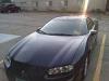
So, I've got the "Service Vehicle" light on in the Camaro, which after some research appears to be related to the BCM throwing codes. This could well be because I've got LED lights and non-standard headlights in the car-not to mention the non-standard tail light wiring job.
I've found a dealer who will read the codes and give them to me at no cost (translating them for me is $92). What I haven't been able to find is a list of the BCM codes themselves. Anybody out there know where I can find such a resource?
(Note, this isn't the Oil Change or the Service Engine Soon light, just mentioning this since I see a lot of confusion regarding these different warning lights in the vehicle. Neither of those lights are on, just the "Service Vehicle" one.)

Overdrive Member
Joined: Nov 2006
Posts: 4,042
From: IL
Yes, GM eSI… Tell me the codes, I can lookup the nitty gritty...
Document ID# 675020
2002 Chevrolet Camaro
Diagnostic Trouble Code (DTC) List
DTC
Diagnostic Procedure
Module(s)
21/31
Diagnostic Trouble Code (DTC) List in Lighting Systems
BCM
22/32
Diagnostic Trouble Code (DTC) List in Lighting Systems
BCM
23/33
Diagnostic Trouble Code (DTC) List in Retained Accessory Power
BCM
24/34
Diagnostic Trouble Code (DTC) List in Restraints
BCM
35 without 25
Diagnostic Trouble Code (DTC) List In Theft Deterrent
BCM
41
Diagnostic Trouble Code (DTC) List in Keyless Entry
BCM
42
Diagnostic Trouble Code (DTC) List in Keyless Entry
BCM
43
Diagnostic Trouble Code (DTC) List in Keyless Entry
BCM
44
Diagnostic Trouble Code (DTC) List in Keyless Entry
BCM
45
Diagnostic Trouble Code (DTC) List in Keyless Entry
BCM
B1000
DTC B1000
EBCM, IPC, PCM, SDM
Document ID# 675020
2002 Chevrolet Camaro
Document ID# 675020
2002 Chevrolet Camaro
Diagnostic Trouble Code (DTC) List
DTC
Diagnostic Procedure
Module(s)
21/31
Diagnostic Trouble Code (DTC) List in Lighting Systems
BCM
22/32
Diagnostic Trouble Code (DTC) List in Lighting Systems
BCM
23/33
Diagnostic Trouble Code (DTC) List in Retained Accessory Power
BCM
24/34
Diagnostic Trouble Code (DTC) List in Restraints
BCM
35 without 25
Diagnostic Trouble Code (DTC) List In Theft Deterrent
BCM
41
Diagnostic Trouble Code (DTC) List in Keyless Entry
BCM
42
Diagnostic Trouble Code (DTC) List in Keyless Entry
BCM
43
Diagnostic Trouble Code (DTC) List in Keyless Entry
BCM
44
Diagnostic Trouble Code (DTC) List in Keyless Entry
BCM
45
Diagnostic Trouble Code (DTC) List in Keyless Entry
BCM
B1000
DTC B1000
EBCM, IPC, PCM, SDM
Document ID# 675020
2002 Chevrolet Camaro
Thread Starter
|
In the Staging Lanes
Joined: Aug 2012
Posts: 54
From: United States
1574 - Stop Lamp switch
I think this is because I have non-standard taillights that don't have the factory wiring setup (plus LEDs in the tail-lights)-could be wrong though.
B0670 - Inflator Reset System
Airbag, I assume?
B0026 - Airbag
They did show me the readouts on the machine, I think I'm pretty close to what they said.
Overdrive Member
Joined: Nov 2006
Posts: 4,042
From: IL
1574 nothing comes up -- are you having lighting problems? Inoperative, stays on, etc.?
Document ID# 683100
2002 Chevrolet Camaro
DTC B0670
Circuit Description
The instrument cluster internally monitors the AIR BAG indicator when power is applied to the instrument cluster. The cluster flashes the indicator seven times during the bulb test and checks the operation of the AIR BAG indicator.
Conditions for Setting the DTC
The instrument cluster detects a failure in the AIR BAG indicator during the bulb test. The cluster will only detect an open AIR BAG indicator.
Action Taken When the DTC Sets
The instrument cluster stores DTC B0670 in memory.
The instrument cluster turns on the Service Vehicle Soon indicator.
Conditions for Clearing the DTC
The condition responsible for setting the DTC no longer exists and the scan tool Clear DTCs function is used.
A history DTC will clear after 255 consecutive ignition cycles if the condition for the malfunction is no longer present.
Diagnostic Aids
DTC B0670 is related to an internal malfunction of the instrument cluster. Attempt to clear the DTC using a scan tool. If the DTC cannot be cleared, replace the instrument cluster. Refer to Instrument Panel Cluster (IPC) Replacement .
Document ID# 683100
2002 Chevrolet Camaro
Document ID# 683100
2002 Chevrolet Camaro
DTC B0670
Circuit Description
The instrument cluster internally monitors the AIR BAG indicator when power is applied to the instrument cluster. The cluster flashes the indicator seven times during the bulb test and checks the operation of the AIR BAG indicator.
Conditions for Setting the DTC
The instrument cluster detects a failure in the AIR BAG indicator during the bulb test. The cluster will only detect an open AIR BAG indicator.
Action Taken When the DTC Sets
The instrument cluster stores DTC B0670 in memory.
The instrument cluster turns on the Service Vehicle Soon indicator.
Conditions for Clearing the DTC
The condition responsible for setting the DTC no longer exists and the scan tool Clear DTCs function is used.
A history DTC will clear after 255 consecutive ignition cycles if the condition for the malfunction is no longer present.
Diagnostic Aids
DTC B0670 is related to an internal malfunction of the instrument cluster. Attempt to clear the DTC using a scan tool. If the DTC cannot be cleared, replace the instrument cluster. Refer to Instrument Panel Cluster (IPC) Replacement .
Document ID# 683100
2002 Chevrolet Camaro
Last edited by libertyforall1776; Sep 9, 2013 at 08:45 PM. Reason: add question
Overdrive Member
Joined: Nov 2006
Posts: 4,042
From: IL
Document ID# 778353
2002 Chevrolet Camaro
DTC B0022, B0024, or B0026
Circuit Description
The inflatable restraint steering wheel module deployment loop consists of the inflatable restraint steering wheel module, the inflatable restraint steering wheel module coil, and the steering wheel module high and low circuits. A shorting bar used within the steering wheel module coil connector shorts together the steering wheel module high and low circuits when the connector is disconnected. This helps to prevent unwanted deployment of the inflator module during servicing. During a frontal collision of sufficient force, the inflatable restraint sensing and diagnostic module (SDM) allows current to flow through the deployment loop in order to deploy the steering wheel module. When the ignition is turned ON, the SDM performs continuous diagnostic tests on the deployment loops to check for proper circuit continuity and for shorts to ground or voltage. If a malfunction is detected, a diagnostic trouble code (DTC) will be stored in memory.
Conditions for Running the DTC
Ignition 1 voltage is within the normal operating voltage range.
Conditions for Setting the DTC
DTC B0022 will set when the steering wheel module deployment loop resistance is less than 1.3 ohms for 300 milliseconds.
DTC B0024 will set when one of the following conditions occur:
Steering wheel module high circuits is more than 6 volts for 300 milliseconds.
Steering wheel module high circuit is less than 2 volts and steering wheel module deployment loop resistance is less than 6 ohms for 300 milliseconds.
DTC B0026 will set when one of the following conditions occurs:
Steering wheel module high circuit is less than 2 volts and the steering wheel module deployment loop is more than 4.8 ohms for 500 milliseconds.
Steering wheel module deployment loop resistance is more than 6 ohms for 300 milliseconds.
Action Taken When the DTC Sets
The SDM commands the AIR BAG indicator ON via Class 2 serial data.
Conditions for Clearing the DTC
The condition responsible for setting the DTC no longer exists and the scan tool Clear DTCs function is used.
A history DTC will clear once 255 malfunction free ignition cycles have occurred.
Diagnostic Aids
The following are possible causes of the malfunction:
A short between the steering wheel module high and low circuits.
An open or a high resistance in the steering wheel module high or low circuits.
A short to ground or a short to voltage in the steering wheel module high or low circuits.
The steering wheel module coil connector
The SDM connector
A malfunctioning steering wheel module
A malfunctioning steering wheel module coil
A malfunctioning SDM
Thoroughly inspect the wiring and the connectors. An incomplete inspection of the wiring and the connectors may result in a misdiagnosis, causing a part replacement with the reappearance of the malfunction. If an intermittent malfunction exists, refer to Testing for Intermittent and Poor Connections in Wiring Systems.
Test Description
The numbers below refer to the step numbers on the diagnostic table.
This step tests to see if the malfunction is caused by the steering wheel module or by the steering wheel module coil.
This step tests to see what DTCs are present. If DTC B0022 is present, test for a short between the steering wheel module high and low circuits. If DTC B0024 is present, test the steering wheel module high and low circuits for an open and for high resistance. If DTC B0026 is present, test the steering wheel module high and low circuits for an open and for high resistance.
Step
Action
Yes
No
Schematic Reference: SIR Schematics
1
Did you perform the Diagnostic System Check - SIR?
Go to Step 2
Go to Diagnostic System Check - SIR
2
Turn OFF the ignition.
Disconnect the steering wheel module coil connector. Refer to Inflatable Restraint Steering Wheel Module Coil Replacement .
Inspect the component and harness sides of the steering wheel module coil connector for damage or corrosion that may cause the malfunction. Refer to Testing for Intermittent and Poor Connections and Connector Repairs in Wiring Systems.
Does the connector exhibit any signs of damage or corrosion?
Go to Step 3
Go to Step 4
3
If the component side of the steering wheel module coil connector is damaged, the steering wheel module coil must be replaced. Refer to Inflatable Restraint Steering Wheel Module Coil Replacement .
If the wiring harness side of steering wheel module coil connector is damaged, replace the harness side of the connector. Refer to Connector Repairs in Wiring Systems.
Did you complete the repair?
Go to Step 11
--
4
Install the J 38715-A SIR Driver/Passenger Load Tool to the harness side of the steering wheel module coil connector. Use BASE OF COLUMN connector.
Turn ON the ignition, with the engine OFF.
Use the scan tool to request SIR DTCs displayed.
Does the scan tool indicate that DTC B0022, B0024, or B0026 are current?
Go to Step 6
Go to Step 5
5
Turn OFF the ignition.
Disconnect and remove the J 38715-A .
Connect the steering wheel module coil connector.
Remove the steering wheel module. Refer to Inflatable Restraint Steering Wheel Module Replacement .
Use the J 38715-30A adapter to connect the J 38715-A to the upper steering wheel module coil connector on top of the steering column. Use STEERING COLUMN connector.
Turn ON the ignition, with the engine OFF.
Use the scan tool to request SIR DTCs displayed.
Does the scan tool indicate that DTC B0022, B0024, or B0026 are current?
Go to Step 9
Go to Step 8
6
Turn OFF the ignition.
Disconnect and remove the J 38715-A and adapter.
Disconnect the inflatable restraint sensing and diagnostic module (SDM) connector. Refer to Inflatable Restraint Sensing and Diagnostic Module Replacement .
Inspect the SDM connector for damage or corrosion that may cause a malfunction in the steering wheel module high and/or low circuits. Refer to Testing for Intermittent and Poor Connections and Connector Repairs in Wiring Systems.
Did you find and correct the condition?
Go to Step 11
Go to Step 7
7
If DTC B0022 is present, test for a short between the steering wheel module high and low circuits.
If DTC B0024 is present, test the steering wheel module high and low circuits for a short to ground or a short to voltage.
If DTC B0026 is present, test the steering wheel module high and low circuits for an open or high resistance.
All the above conditions refer to Circuit Testing and Wiring Repairs in Wiring Systems.
Did you find and correct the condition?
Go to Step 11
Go to Step 10
8
Turn OFF the ignition.
Replace the steering wheel module. Refer to Inflatable Restraint Steering Wheel Module Replacement .
Did you complete the replacement?
Go to Step 11
--
9
Turn OFF the ignition.
Replace the steering wheel module coil. Refer to Inflatable Restraint Steering Wheel Module Coil Replacement .
Did you complete the replacement?
Go to Step 11
--
10
Turn OFF the ignition.
Replace the SDM. Refer to Inflatable Restraint Sensing and Diagnostic Module Replacement .
Did you complete the replacement?
Go to Step 11
--
11
Connect all SIR components.
Turn ON the ignition, with the engine OFF.
Use the scan tool in order to clear the DTCs.
Operate the vehicle within the Conditions for Running the DTC as specified in the supporting text.
Does the DTC reset?
Go to Step 2
System OK
Document ID# 778353
2002 Chevrolet Camaro
2002 Chevrolet Camaro
DTC B0022, B0024, or B0026
Circuit Description
The inflatable restraint steering wheel module deployment loop consists of the inflatable restraint steering wheel module, the inflatable restraint steering wheel module coil, and the steering wheel module high and low circuits. A shorting bar used within the steering wheel module coil connector shorts together the steering wheel module high and low circuits when the connector is disconnected. This helps to prevent unwanted deployment of the inflator module during servicing. During a frontal collision of sufficient force, the inflatable restraint sensing and diagnostic module (SDM) allows current to flow through the deployment loop in order to deploy the steering wheel module. When the ignition is turned ON, the SDM performs continuous diagnostic tests on the deployment loops to check for proper circuit continuity and for shorts to ground or voltage. If a malfunction is detected, a diagnostic trouble code (DTC) will be stored in memory.
Conditions for Running the DTC
Ignition 1 voltage is within the normal operating voltage range.
Conditions for Setting the DTC
DTC B0022 will set when the steering wheel module deployment loop resistance is less than 1.3 ohms for 300 milliseconds.
DTC B0024 will set when one of the following conditions occur:
Steering wheel module high circuits is more than 6 volts for 300 milliseconds.
Steering wheel module high circuit is less than 2 volts and steering wheel module deployment loop resistance is less than 6 ohms for 300 milliseconds.
DTC B0026 will set when one of the following conditions occurs:
Steering wheel module high circuit is less than 2 volts and the steering wheel module deployment loop is more than 4.8 ohms for 500 milliseconds.
Steering wheel module deployment loop resistance is more than 6 ohms for 300 milliseconds.
Action Taken When the DTC Sets
The SDM commands the AIR BAG indicator ON via Class 2 serial data.
Conditions for Clearing the DTC
The condition responsible for setting the DTC no longer exists and the scan tool Clear DTCs function is used.
A history DTC will clear once 255 malfunction free ignition cycles have occurred.
Diagnostic Aids
The following are possible causes of the malfunction:
A short between the steering wheel module high and low circuits.
An open or a high resistance in the steering wheel module high or low circuits.
A short to ground or a short to voltage in the steering wheel module high or low circuits.
The steering wheel module coil connector
The SDM connector
A malfunctioning steering wheel module
A malfunctioning steering wheel module coil
A malfunctioning SDM
Thoroughly inspect the wiring and the connectors. An incomplete inspection of the wiring and the connectors may result in a misdiagnosis, causing a part replacement with the reappearance of the malfunction. If an intermittent malfunction exists, refer to Testing for Intermittent and Poor Connections in Wiring Systems.
Test Description
The numbers below refer to the step numbers on the diagnostic table.
This step tests to see if the malfunction is caused by the steering wheel module or by the steering wheel module coil.
This step tests to see what DTCs are present. If DTC B0022 is present, test for a short between the steering wheel module high and low circuits. If DTC B0024 is present, test the steering wheel module high and low circuits for an open and for high resistance. If DTC B0026 is present, test the steering wheel module high and low circuits for an open and for high resistance.
Step
Action
Yes
No
Schematic Reference: SIR Schematics
1
Did you perform the Diagnostic System Check - SIR?
Go to Step 2
Go to Diagnostic System Check - SIR
2
Turn OFF the ignition.
Disconnect the steering wheel module coil connector. Refer to Inflatable Restraint Steering Wheel Module Coil Replacement .
Inspect the component and harness sides of the steering wheel module coil connector for damage or corrosion that may cause the malfunction. Refer to Testing for Intermittent and Poor Connections and Connector Repairs in Wiring Systems.
Does the connector exhibit any signs of damage or corrosion?
Go to Step 3
Go to Step 4
3
If the component side of the steering wheel module coil connector is damaged, the steering wheel module coil must be replaced. Refer to Inflatable Restraint Steering Wheel Module Coil Replacement .
If the wiring harness side of steering wheel module coil connector is damaged, replace the harness side of the connector. Refer to Connector Repairs in Wiring Systems.
Did you complete the repair?
Go to Step 11
--
4
Install the J 38715-A SIR Driver/Passenger Load Tool to the harness side of the steering wheel module coil connector. Use BASE OF COLUMN connector.
Turn ON the ignition, with the engine OFF.
Use the scan tool to request SIR DTCs displayed.
Does the scan tool indicate that DTC B0022, B0024, or B0026 are current?
Go to Step 6
Go to Step 5
5
Turn OFF the ignition.
Disconnect and remove the J 38715-A .
Connect the steering wheel module coil connector.
Remove the steering wheel module. Refer to Inflatable Restraint Steering Wheel Module Replacement .
Use the J 38715-30A adapter to connect the J 38715-A to the upper steering wheel module coil connector on top of the steering column. Use STEERING COLUMN connector.
Turn ON the ignition, with the engine OFF.
Use the scan tool to request SIR DTCs displayed.
Does the scan tool indicate that DTC B0022, B0024, or B0026 are current?
Go to Step 9
Go to Step 8
6
Turn OFF the ignition.
Disconnect and remove the J 38715-A and adapter.
Disconnect the inflatable restraint sensing and diagnostic module (SDM) connector. Refer to Inflatable Restraint Sensing and Diagnostic Module Replacement .
Inspect the SDM connector for damage or corrosion that may cause a malfunction in the steering wheel module high and/or low circuits. Refer to Testing for Intermittent and Poor Connections and Connector Repairs in Wiring Systems.
Did you find and correct the condition?
Go to Step 11
Go to Step 7
7
If DTC B0022 is present, test for a short between the steering wheel module high and low circuits.
If DTC B0024 is present, test the steering wheel module high and low circuits for a short to ground or a short to voltage.
If DTC B0026 is present, test the steering wheel module high and low circuits for an open or high resistance.
All the above conditions refer to Circuit Testing and Wiring Repairs in Wiring Systems.
Did you find and correct the condition?
Go to Step 11
Go to Step 10
8
Turn OFF the ignition.
Replace the steering wheel module. Refer to Inflatable Restraint Steering Wheel Module Replacement .
Did you complete the replacement?
Go to Step 11
--
9
Turn OFF the ignition.
Replace the steering wheel module coil. Refer to Inflatable Restraint Steering Wheel Module Coil Replacement .
Did you complete the replacement?
Go to Step 11
--
10
Turn OFF the ignition.
Replace the SDM. Refer to Inflatable Restraint Sensing and Diagnostic Module Replacement .
Did you complete the replacement?
Go to Step 11
--
11
Connect all SIR components.
Turn ON the ignition, with the engine OFF.
Use the scan tool in order to clear the DTCs.
Operate the vehicle within the Conditions for Running the DTC as specified in the supporting text.
Does the DTC reset?
Go to Step 2
System OK
Document ID# 778353
2002 Chevrolet Camaro
Overdrive Member
Joined: Nov 2006
Posts: 4,042
From: IL
^ Aha! 
Document ID# 774133
2002 Chevrolet Camaro
DTC P1574
Circuit Description
This diagnostic test functions on the assumption that sudden decrease in a non-drive, wheel speed must be caused by a brake application. Non-drive wheel speed and stoplamp switch status are supplied to the PCM through serial data from the Electronic Brake Control Module (EBCM). If there is a 4 km/h (2.5 mph) or greater decrease of non-drive wheel speed in 0.4 seconds and a transition of the TCC or extended travel contacts of the TCC brake switch without a transition of the stop lamp brake switch, DTC P1574 is set.
Conditions for Running the DTC
DTCs P0502, P0503, P0719, P0724, P1575 and P1602 not set.
Traction control and antilock brake systems have not failed.
Traction control and antilock brake systems are not active.
Non-drive wheel speed goes above 32.2 km/h (20 mph) and then doesn't go below 6.4 km/h (4 mph).
Conditions for Setting the DTC
A 4.0 km/h (2.5 mph) or greater decrease in non-drive wheel speed in 0.4 second and extended travel brake switch or TCC brake switch indicating brakes applied and no transition noticed in the stoplamp contacts of the stop lamp switch.
Action Taken When the DTC Sets
PCM will set the stoplamp switch status to not applied.
The Malfunction Indicator Lamp (MIL) will not illuminate.
No message will be displayed.
Conditions for Clearing the DTC
A History DTC will clear after forty consecutive warm-up cycles with no failures of any non-emission related diagnostic test.
A Last Test Failed (current) DTC will clear when the diagnostic runs and does not fail.
Use a scan tool to clear DTCs.
Interrupting PCM battery voltage may or may not clear DTCs. This practice is not recommended.
Diagnostic Aids
DTC P1574 indicates the stoplamp switch signal to the EBCM or the EBCM's ability to send the stop lamp switch signal to the PCM has failed. Refer to ABS/TCS DTCs for diagnosis of the stoplamp switch signal and the EBCM.
Step
Action
Yes
No
1
Did you perform the Cruise Control Diagnostic System Check?
Go to Step 2
Go to Diagnostic System Check - Cruise Control
2
Connect the scan tool.
Turn ON the ignition, with the engine OFF.
Retrieve the DTCs from the EBCM.
Are there any DTC's that begin with a "C" also set?
Go to Diagnostic Trouble Code (DTC) List
Go to Step 3
3
Repair the short to voltage on the stop lamp switch signal circuit.
Did you find and correct the condition?
Go to Step 4
--
4
Use the scan tool to clear the DTC (s).
Operate the vehicle within the conditions for Running the DTC as specified in the supporting text.
Does the DTC reset?
Go to Step 2
System OK
Document ID# 774133
2002 Chevrolet Camaro
Document ID# 774133
2002 Chevrolet Camaro
DTC P1574
Circuit Description
This diagnostic test functions on the assumption that sudden decrease in a non-drive, wheel speed must be caused by a brake application. Non-drive wheel speed and stoplamp switch status are supplied to the PCM through serial data from the Electronic Brake Control Module (EBCM). If there is a 4 km/h (2.5 mph) or greater decrease of non-drive wheel speed in 0.4 seconds and a transition of the TCC or extended travel contacts of the TCC brake switch without a transition of the stop lamp brake switch, DTC P1574 is set.
Conditions for Running the DTC
DTCs P0502, P0503, P0719, P0724, P1575 and P1602 not set.
Traction control and antilock brake systems have not failed.
Traction control and antilock brake systems are not active.
Non-drive wheel speed goes above 32.2 km/h (20 mph) and then doesn't go below 6.4 km/h (4 mph).
Conditions for Setting the DTC
A 4.0 km/h (2.5 mph) or greater decrease in non-drive wheel speed in 0.4 second and extended travel brake switch or TCC brake switch indicating brakes applied and no transition noticed in the stoplamp contacts of the stop lamp switch.
Action Taken When the DTC Sets
PCM will set the stoplamp switch status to not applied.
The Malfunction Indicator Lamp (MIL) will not illuminate.
No message will be displayed.
Conditions for Clearing the DTC
A History DTC will clear after forty consecutive warm-up cycles with no failures of any non-emission related diagnostic test.
A Last Test Failed (current) DTC will clear when the diagnostic runs and does not fail.
Use a scan tool to clear DTCs.
Interrupting PCM battery voltage may or may not clear DTCs. This practice is not recommended.
Diagnostic Aids
DTC P1574 indicates the stoplamp switch signal to the EBCM or the EBCM's ability to send the stop lamp switch signal to the PCM has failed. Refer to ABS/TCS DTCs for diagnosis of the stoplamp switch signal and the EBCM.
Step
Action
Yes
No
1
Did you perform the Cruise Control Diagnostic System Check?
Go to Step 2
Go to Diagnostic System Check - Cruise Control
2
Connect the scan tool.
Turn ON the ignition, with the engine OFF.
Retrieve the DTCs from the EBCM.
Are there any DTC's that begin with a "C" also set?
Go to Diagnostic Trouble Code (DTC) List
Go to Step 3
3
Repair the short to voltage on the stop lamp switch signal circuit.
Did you find and correct the condition?
Go to Step 4
--
4
Use the scan tool to clear the DTC (s).
Operate the vehicle within the conditions for Running the DTC as specified in the supporting text.
Does the DTC reset?
Go to Step 2
System OK
Document ID# 774133
2002 Chevrolet Camaro

2nd Gear member
Joined: Aug 2013
Posts: 509
By the way, none of the codes you listed are coming from the BCM. The first one is from the PCM and the others are from the SIR(airbags). Whoever retrieved the codes for you evidently checked all modules.
If you are interested anyway, you can easily retrieve/flash BCM codes yourself using the procedure in the free 2000 manual at this location: My Files
If you are interested anyway, you can easily retrieve/flash BCM codes yourself using the procedure in the free 2000 manual at this location: My Files
Thread Starter
|
In the Staging Lanes
Joined: Aug 2012
Posts: 54
From: United States
The brakes/turn signals/reverse lights are all functioning normally. I'm pretty confident the stop lamp code is due to the fact that the LED rings in the tail lights required a couple of splices in the wiring-or it's because the brake lights are using LEDs instead of the standard bulbs. I'll make a note of the code explanation though. I'm thinking that one might be able to be tuned out.
Regarding the other two, that information is very helpful. Thank you both for your comments and the provision of an excellent explanation of what those codes mean, I appreciate it greatly! Also helpful to know that those aren't the BCM codes like I thought. I'll take a look at the BCM code manual your reference later, when it isn't so late. Thanks again!
Regarding the other two, that information is very helpful. Thank you both for your comments and the provision of an excellent explanation of what those codes mean, I appreciate it greatly! Also helpful to know that those aren't the BCM codes like I thought. I'll take a look at the BCM code manual your reference later, when it isn't so late. Thanks again!