
1999 no start problem
#1
 08-04-2013, 03:58 PM


I've read several posts about this problem but I haven't found any solutions. Here is my problem my son's 3.8 will turn over but not hit. We have fuel pressure (around 50 psig) but no spark. Our Haynes manual explained t how to check the ignition module, this is where there info stopped. On the pink wire with the key switch off there is 12 volts but when you turn the key to the on position we lose voltage. From what I hear that's backwards. any ideas?

#3
08-04-2013, 06:24 PM
If you are referring to the ignition relay in the fuse box, it working correctly and the fuses are good. I can test for voltage at the fuse and it is "hot" all of the time. That's what is confusing me, according to the wiring diagram when the key is turned to on that is what energizes the relay passing power to the ignition module. But the voltage goes away on the pink wire, which appears to be the power wire for the ignition module. Something else when we started our diagnosis we found the plug to the ignition module to be burnt in two places next together. Counting the pink wire as number one they were either #3 and #4 or #4 and #5.
#4
08-04-2013, 06:54 PM

Join Date: Mar 2009
Location: Tokeland, Washington
Posts: 21,750
you have two fuse boxes. there should be a ingnition (ign) fuse in the one on the side of the dash. ignition switch is on the steering coluum down by your feet. 4th Gen F-body Ignition Switch Replacement
download a factory manual here, its a few big files for your year. https://camaroforums.com/forum/camar...d-views-73894/
download a factory manual here, its a few big files for your year. https://camaroforums.com/forum/camar...d-views-73894/
#6
08-04-2013, 07:26 PM
I just went out to check the fuse in the dash. I found a location on the fuse usage chart , the diagram of where the fuses are located, for IGN but no fuse just a "L" shaped hole. Could it be called something else?
#7
08-04-2013, 07:59 PM
Join Date: Mar 2009
Location: Tokeland, Washington
Posts: 21,750
lets see, 99, look for pcm, 99 may not have a ignition fuse, i have a no start chart for lt1 and 3.4 for 93-97. 99 3.8 should be in the manual. takes a while to download. i did 94 book 1 to see how long it took with my old mac and will do the rest some evening when not not so busy and can remember to do it.  then maybe start on the 99 book. did you get the burnt wires all sorted out? and maybe try switching the relay with one of the other ones, not the abs one its the one thats different, at least it is on mine. im hoping massey or gorn will see this, they know more about the obd2 system than i.
then maybe start on the 99 book. did you get the burnt wires all sorted out? and maybe try switching the relay with one of the other ones, not the abs one its the one thats different, at least it is on mine. im hoping massey or gorn will see this, they know more about the obd2 system than i.
#8
08-04-2013, 08:34 PM
We replaced the plug and ignition module, soldiered the wires with heat shrink over that. I tried using another relay from a fan but that didn't work. I tested the relay and it switched outputs as it should. I'm by no means a auto mechanic, just educated enough to be dangerous, I'm a commercial HVAC tech so I'm used to looking at wiring diagrams. But this DC system is kicking my butt! Thanks for your help so far, I am grateful.
#9
08-05-2013, 09:45 AM

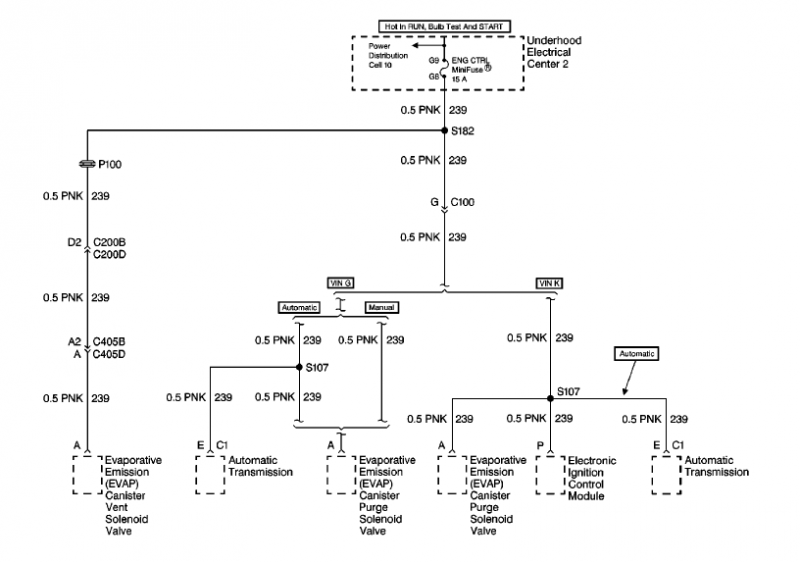
After sorting what Craby was kind enough to post it looks like these 2 diagrams are what we need.
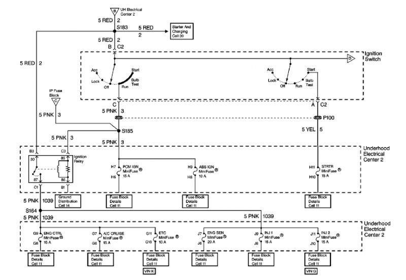
One question before I make a few suggestions. When you are testing the pink wire under the hood what are you using for ground? Are you using the frame/motor/battery negative or are you using another wire for your negative for the meter?
Sounds like we need to find a break in the chain somewhere so I would start at the end and work my way back.
We know you do not have voltage at the ICM so meter the fuse under the hood labeled "ENG CTRL" (use the battery or frame for your negative connection and touch each side of the fuse to see if you have 12v on both sides). If you have 12V on both sides than there may be a break in the wire under the hood somewhere running to the ICM.
If you do not have 12V on both sides of the fuse check the fuse to make sure it has 0 ohms or continuity (take it out first because if you meter it in place you can get a false reading and I have had fuses that pass a visual inspection but are bad) if the fuse is fine than we will need to meter the pins for the "Ignition Relay socket".
The pins should be as follows:
-30 should have 12V all the time
-87 is the output so doesn�t matter right now
-85 should have 12V with the ignition on
-86 should have continuity or 0 ohms at all times since this is your ground
If all that checks out and is spot on than I would run a jumper from pin 30 to pin 87 and try to start the car if it starts than you have a bad relay and requires replacement.
If you do not have power on pin 30 or 85 then we can dig in a little further. If you are missing either - meter the wire harness at the ignition switch for the following. Check the reds for 12V with the car off and meter the pink (you should have 12v with key on).
Sorry if some of this is redundant or things you already know... I just try not to assume.