
Voltage Regulator diode? / Wire harness


Thread Starter
|
2nd Gear member
Joined: Jan 2011
Posts: 351
From: Michigan
This is the wire harness between the grill and the Rad support. Not sure where I'm supposed t route the harness to hide it and make it look good.
BTW, All of this has been freshly painted, it's just extreemly dusty.
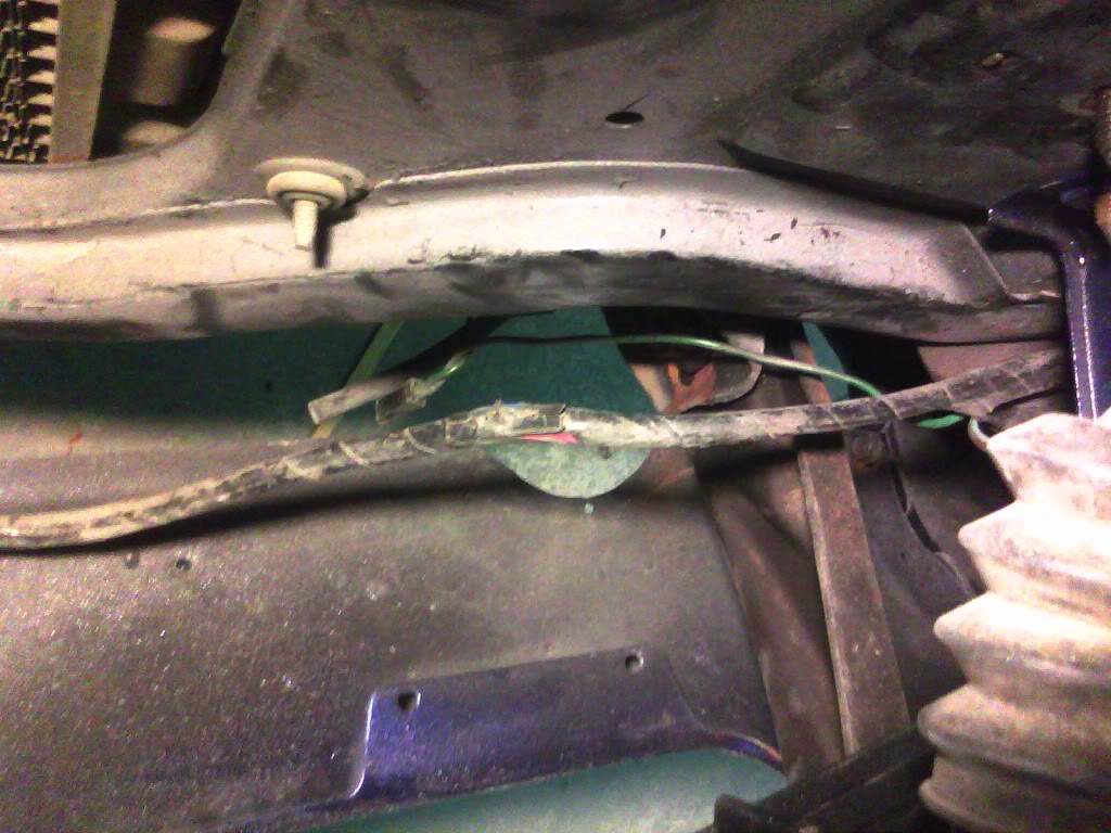
According to the schematic, this parking light is supposed to be grounded. I can confirm this because the parking lights won't work until I ground it.
Can somebody look at theirs and tell me how your's is grounded?
BTW, All of this has been freshly painted, it's just extreemly dusty.
According to the schematic, this parking light is supposed to be grounded. I can confirm this because the parking lights won't work until I ground it.
Can somebody look at theirs and tell me how your's is grounded?

In the Staging Lanes
Joined: Dec 2009
Posts: 48
From: In Orocker's Camaro
since you have the 1 wire alternator already.....remove the wiring section for the voltage regulator and go single wire. Solves the whole problem and cuts down on things that can go wrong in the charging system (the newer voltage regulators inside the alternators are better than the old ones).
We ran the wiring in front of the radiator under the U channel of the radiator support and zip tied it to that. I believe though that the correct routing is zip tied or bolted to the bottom of the radiator support. We were trying to hide as many wires as possible and routed the wiring slightly different.
We ran the wiring in front of the radiator under the U channel of the radiator support and zip tied it to that. I believe though that the correct routing is zip tied or bolted to the bottom of the radiator support. We were trying to hide as many wires as possible and routed the wiring slightly different.
Thread Starter
|
2nd Gear member
Joined: Jan 2011
Posts: 351
From: Michigan
Squid, The more I think abut it, I'm thinking your right on switching over to the 1 wire setup for the Alt and just ditching the VR. I was a bit resistant just because electrical and I don't get along (I'm somewhat color blind). It will be a little extra work, but I think it will look much, much cleaner.
Did I ever tell anyone I hate electrical?
Did I ever tell anyone I hate electrical?

December 2011 ROTM
Santas Little Helper
Santas Little Helper
Joined: Jul 2007
Posts: 1,242
From: Casselberry, FL
ROTM Winner's Club
haha I have no clue how to do any of this stuff. I just stand there and take pics of him doing it. I have learned a lot though.

December 2010 ROTM
Joined: Dec 2009
Posts: 441
From: Illinois
ROTM Winner's Club
electrical SUCKS!!!!!!!!!!!!!!!!
LOL
you will need the horn relay even with the single wire alt. setup
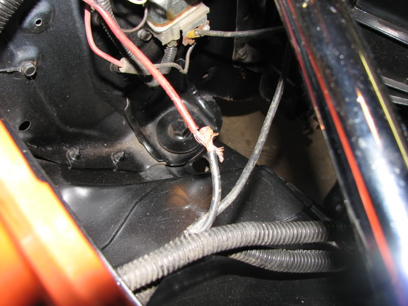
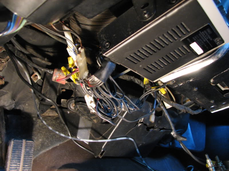
i had some issues with mine as well they had tapped into the main power wire and ran a 6 foot power wire into the car to an ammeter and back out 6 ft to the horn relay!!??? it would arc when bumped the wrong way!!
here was mine before i removed said wire and the 80`s sterio mess under the dash!!!
LOL
you will need the horn relay even with the single wire alt. setup
i had some issues with mine as well they had tapped into the main power wire and ran a 6 foot power wire into the car to an ammeter and back out 6 ft to the horn relay!!??? it would arc when bumped the wrong way!!
here was mine before i removed said wire and the 80`s sterio mess under the dash!!!
Thread Starter
|
2nd Gear member
Joined: Jan 2011
Posts: 351
From: Michigan
Really though, I can't tell green from brown, and some browns with red or purple from dark blue... especially on old 40 year old wiring. Hence my hesitance if you know what I mean. When I wired the Alt, I had to have my wife tell me which color was what since the original Alt connection was missing.
Thread Starter
|
2nd Gear member
Joined: Jan 2011
Posts: 351
From: Michigan
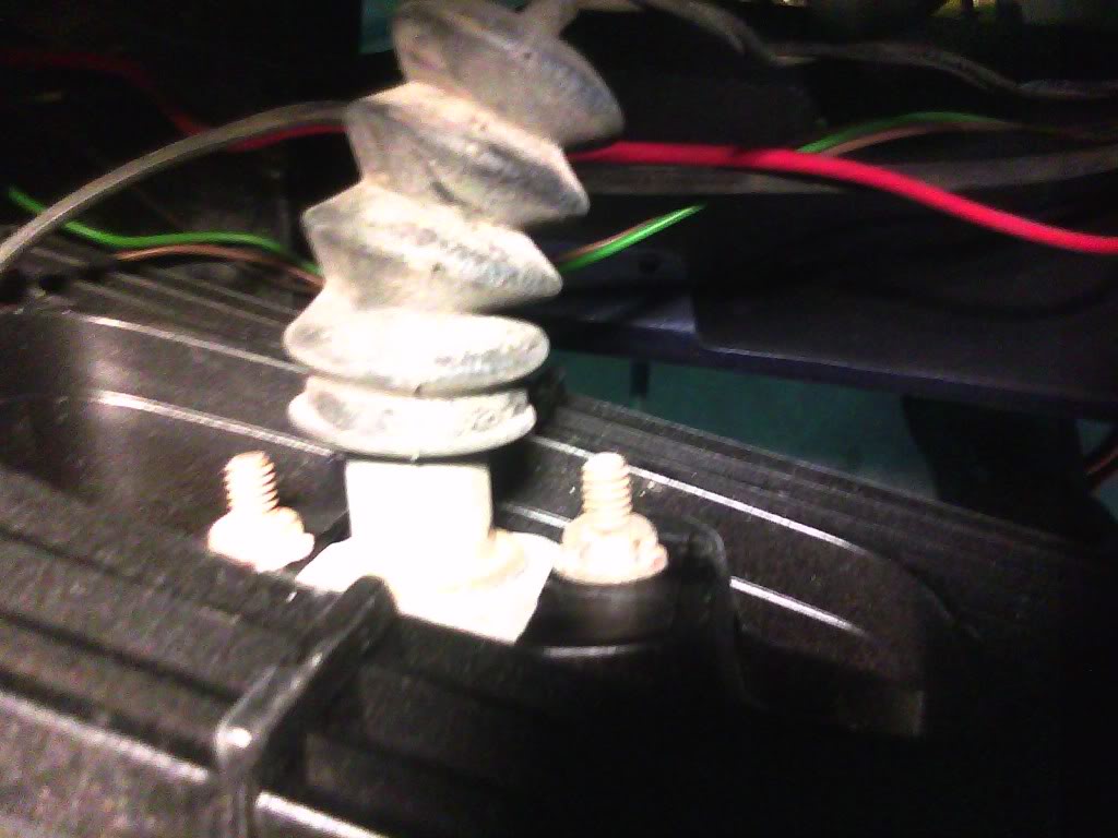
Speaking of Alternators... I took this picture last night too. Again, you'll have to excuse the dust... she's been sitting a few years.
Anyway, this should be interesting to clean up the two extra wires I won't be needing. I just wish I had kept the instructions on this Alternator for a single wire setup...
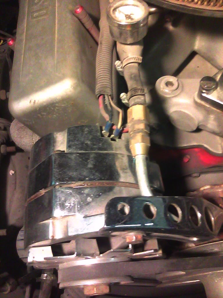
Anyway, this should be interesting to clean up the two extra wires I won't be needing. I just wish I had kept the instructions on this Alternator for a single wire setup...

In the Staging Lanes
Joined: Sep 2010
Posts: 74
Was looking in the assembly manual and I noticed that the regulator body is grounded. In UPC U63 sheet A4 it clearly shows the capacitor grounded to the body of the regulator sandwiching a ground wire (to ensure a good ground).
I want to help you with the running lights but mine is not all the way together... yet... especially the electrical.
Still working on that.
I want to help you with the running lights but mine is not all the way together... yet... especially the electrical.
Still working on that.
December 2010 ROTM
Joined: Dec 2009
Posts: 441
From: Illinois
ROTM Winner's Club
Speaking of Alternators... I took this picture last night too. Again, you'll have to excuse the dust... she's been sitting a few years.
Anyway, this should be interesting to clean up the two extra wires I won't be needing. I just wish I had kept the instructions on this Alternator for a single wire setup...
Anyway, this should be interesting to clean up the two extra wires I won't be needing. I just wish I had kept the instructions on this Alternator for a single wire setup...
just snip all the ends off the 3 wires goin to the alt. electric tape each end and then bundle and retape again then find a good place to tuck/hide them just incase you decide to use them down the road.
you will need a larger single wire for the one from alt. to battery that goes from alter. rear post to positive cable at batt.
thats it done.
Thread Starter
|
2nd Gear member
Joined: Jan 2011
Posts: 351
From: Michigan
So it's as simple as removing all three wires from the alt, unplugging and removing the VR and running a wire from the ALT to the positive side of the battery? That's it?
BTW, it makes since that it would be the "fat" wire on the ALT that goes to the positive battery cable LOL. Why do I confuse things Have I told you I hate electrical?
BTW, it makes since that it would be the "fat" wire on the ALT that goes to the positive battery cable LOL. Why do I confuse things