
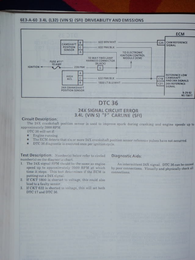
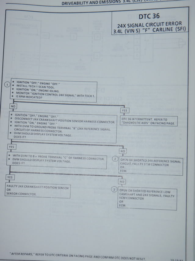
OBD1 code 36
#1
 02-15-2010 | 11:21 AM
Thread Starter
|
2nd Gear member
Joined: Sep 2008
Posts: 472
From: Las Vegas NV
ok im getting this error and want to fix it.
i have a 95 3.4 5 spd and ive already replaced the crankshaft position sensor so whats next now?
i know the 24x signal error could be anything from the coil packs to the sensors.
i plan on testing the coils soon and i didnt know if i should also replace the camshaft sensor?
i have a 95 3.4 5 spd and ive already replaced the crankshaft position sensor so whats next now?
i know the 24x signal error could be anything from the coil packs to the sensors.
i plan on testing the coils soon and i didnt know if i should also replace the camshaft sensor?

#4
02-15-2010 | 03:15 PM
Thread Starter
|
2nd Gear member
Joined: Sep 2008
Posts: 472
From: Las Vegas NV
From what I remember there was only one in the diagram I found. I'll check again but I only replaced 1. Some of the wires on coil pack look like the insulation has been cut a little. Should I just wrap it in electrical tape or put a little solder on it then wrap it?
Thanks for the pic now I know what to do lol
Thanks for the pic now I know what to do lol


#6
02-15-2010 | 04:13 PM

Overdrive Member
Joined: Nov 2006
Posts: 4,042
From: IL
You mean your spark plug wires? If those are the wires you're talking about, I would replace the damaged ones, or all if you haven't done so in a long time (many mi.).
From what I remember there was only one in the diagram I found. I'll check again but I only replaced 1. Some of the wires on coil pack look like the insulation has been cut a little. Should I just wrap it in electrical tape or put a little solder on it then wrap it?
Thanks for the pic now I know what to do lol
Thanks for the pic now I know what to do lol
#7
02-15-2010 | 04:16 PM

April 2011 ROTM

Joined: Mar 2009
Posts: 21,768
From: Tokeland, Washington
ROTM Winner's Club
liberty i can see them. am i the only one that can. i wonder what the heck it is. there fixed it. i moved the pictures and after i posted. still learning with the photobucket thing.
there is a cam sensor and a crank sensor in the 93.
there is a cam sensor and a crank sensor in the 93.
Last edited by craby; 02-15-2010 at 04:21 PM.
#8
02-15-2010 | 04:22 PM
Overdrive Member
Joined: Nov 2006
Posts: 4,042
From: IL
This might help (but is for the 3.8L, concepts should be similar, though):
Document ID# 1241712
1995 Chevrolet/Geo Camaro
DTC P0336 Crankshaft Position (CKP) Sensor Circuit
Circuit Description
The 18X reference signal is produced by the ignition control module. The ICM calculates the 18X reference signal by filtering the crankshaft position (CKP) sensor 18X pulses when the engine is running and CKP sync pulses are also being received. The PCM uses the 18X reference signal to calculate engine RPM and crankshaft position at engine speeds below 1200 RPM. The PCM constantly monitors the number of pulses on the 18X reference circuit and compares the number of 18X reference pulses to the number of 3 X reference pulses and CAM signal pulses being received. If the PCM receives an incorrect number of pulses on the 18X reference circuit, DTC P0336 will set and the PCM will use the 3X reference signal circuit for fuel and ignition control. The engine will continue to start and run using the 3X reference and CAM signals only.
Conditions for Setting the DTC
* The engine is running (3X reference pulses are being received).
* The ratio of 18X reference pulses to 3X reference pulses received by the PCM does not equal 6 to 1.
* The ratio of 3X reference pulses to CAM signal pulses received by the PCM equals 6 to 1.
* Above conditions for 290 occurrences.
Action Taken When the DTC Sets
* The PCM will illuminate the MIL during the second consecutive trip in which the diagnostic test has been run and failed.
* The PCM will use the 3X reference signal circuit for fuel and ignition control.
* If equipped with traction control, the PCM will command the EBTCM via serial data (CKT 800) to set an ABS/TCS DTC, the EBTCM will turn OFF traction control, and the EBTCM will illuminate the TRACTION OFF lamp.
* The PCM will store conditions which were present when the DTC set as Freeze Frame and Fail Records data.
Conditions for Clearing the MIL/DTC
* The PCM will turn OFF the MIL during the third consecutive trip in which the diagnostic has been run and passed.
* The History DTC will clear after 40 consecutive warm-up cycles have occurred without a malfunction.
* The DTC can be cleared by using the scan tool.
Diagnostic Aids
An intermittent may be caused by a poor connection, rubbed through wire insulation or a wire broken inside the insulation. Check for the following conditions:
* Poor connection. Inspect the PCM harness and connectors for improper mating, broken locks, improperly formed or damaged terminals, and poor terminal to wire connection.
* Damaged harness. Inspect the wiring harness for damage. If the harness appears to be OK, disconnect the PCM, turn the ignition on and observe a voltmeter connected to the 18X reference circuit at the PCM harness connector while moving connectors and wiring harnesses related to the ICM. A change in voltage will indicate the location of the malfunction.
* Incorrect harness routing near secondary ignition components.
* Malfunctioning Ignition Coil. Remove the ignition coils and inspect the ignition control module and coils for cracks, carbon tracking, or other signs that indicate that the coil secondary circuit is arcing to the ICM or ICM wiring harness. Refer to Ignition Control Module Replacement .
* Secondary ignition wire(s) arcing to wiring harness. Check secondary ignition wires for carbon tracking or other signs of damage.
Reviewing the Fail Records vehicle mileage since the diagnostic test last failed may help determine how often the condition that caused the DTC to be set occurs. This may assist in diagnosing the condition.
Test Description
The numbers below refer to the step numbers on the Diagnostic Table.
10.
This vehicle is equipped with a PCM which utilizes an electrically erasable programmable read only memory (EEPROM). When the PCM is being replaced, the new PCM must be programmed.
Step
Action
Value(s)
Yes
No
Schematic Reference: Engine Controls Schematics
1
Was the Powertrain On-Board Diagnostic (OBD) System Check performed?
--
Go to Step 2
Go to the Powertrain On Board Diagnostic (OBD) System Check
2
Attempt to start the engine.
Does the engine start?
--
Go to Step 3
Go to Engine Cranks but Does Not Run
3
1. Review and record scan tool Fail Records data.
2. Clear DTC P0336.
3. Start the engine and idle for 1 minute.
4. Observe DTC(s).
Is DTC P0336 set?
--
Go to Step 4
Goto Diagnostic Aids
4
1. Turn OFF the ignition switch.
2. Disconnect the ignition control module.
3. Disconnect the PCM.
4. Check for an open or a short to ground in the 18X reference circuit between the ignition control module harness connector and the PCM harness connector.
5. If a problem is found, repair as necessary. Refer to Wiring Repairs in Electrical Diagnosis.
Was a problem found?
--
Go to Step 11
Go to Step 5
5
1. Reconnect the ignition control module.
2. Connect a DVM to measure voltage on the 18X reference circuit at the PCM connector.
3. Observe the voltage while cranking the engine.
Is voltage near the specified value?
3V
Go to Step 8
Go to Step 6
6
Check connections at the ignition control module and replace terminals if necessary. Refer to Wiring Repairs in Electrical Diagnosis.
Did any terminals require replacement?
--
Go to Step 11
Go to Step 7
7
Replace the ignition control module. Refer to Ignition Control Module Replacement .
Is action complete?
--
Go to Step 11
--
8
1. Check for the following conditions:
* Incorrect harness routing near secondary ignition components.
* Ignition coil arcing to the wiring harness or to the ignition control module (check ignition coils for cracks, carbon tracking, or other signs of damage). Refer to Ignition Control Module Replacement .
* Secondary ignition wires arcing to the wiring Harness. Refer to Secondary Wiring in Ignition System.
2. If a problem is found, repair as necessary.
Was a problem found?
--
Go to Step 11
Go to Step 9
9
Check connections at the PCM and replace terminals if necessary. Refer to Wiring Repair in Electrical Diagnosis.
Did any terminals require replacement?
--
Go to Step 11
Go to Step 10
10
Replace the PCM.
Important:
The replacement PCM must be programmed. Refer to PCM Replacement/Programming .
Is action complete?
--
Go to Step 11
--
11
1. Review and record scan tool Fail Records data.
2. Clear DTCs.
3. Operate vehicle within Fail Records conditions as noted.
4. Using a scan tool, monitor Specific DTC info for DTC P0336 until the DTC P0336 test runs.
Does scan tool indicate DTC P0336 failed this ignition?
--
Go to Step 2
System OK
Document ID# 1241712
1995 Chevrolet/Geo Camaro
Document ID# 1241712
1995 Chevrolet/Geo Camaro
DTC P0336 Crankshaft Position (CKP) Sensor Circuit
Circuit Description
The 18X reference signal is produced by the ignition control module. The ICM calculates the 18X reference signal by filtering the crankshaft position (CKP) sensor 18X pulses when the engine is running and CKP sync pulses are also being received. The PCM uses the 18X reference signal to calculate engine RPM and crankshaft position at engine speeds below 1200 RPM. The PCM constantly monitors the number of pulses on the 18X reference circuit and compares the number of 18X reference pulses to the number of 3 X reference pulses and CAM signal pulses being received. If the PCM receives an incorrect number of pulses on the 18X reference circuit, DTC P0336 will set and the PCM will use the 3X reference signal circuit for fuel and ignition control. The engine will continue to start and run using the 3X reference and CAM signals only.
Conditions for Setting the DTC
* The engine is running (3X reference pulses are being received).
* The ratio of 18X reference pulses to 3X reference pulses received by the PCM does not equal 6 to 1.
* The ratio of 3X reference pulses to CAM signal pulses received by the PCM equals 6 to 1.
* Above conditions for 290 occurrences.
Action Taken When the DTC Sets
* The PCM will illuminate the MIL during the second consecutive trip in which the diagnostic test has been run and failed.
* The PCM will use the 3X reference signal circuit for fuel and ignition control.
* If equipped with traction control, the PCM will command the EBTCM via serial data (CKT 800) to set an ABS/TCS DTC, the EBTCM will turn OFF traction control, and the EBTCM will illuminate the TRACTION OFF lamp.
* The PCM will store conditions which were present when the DTC set as Freeze Frame and Fail Records data.
Conditions for Clearing the MIL/DTC
* The PCM will turn OFF the MIL during the third consecutive trip in which the diagnostic has been run and passed.
* The History DTC will clear after 40 consecutive warm-up cycles have occurred without a malfunction.
* The DTC can be cleared by using the scan tool.
Diagnostic Aids
An intermittent may be caused by a poor connection, rubbed through wire insulation or a wire broken inside the insulation. Check for the following conditions:
* Poor connection. Inspect the PCM harness and connectors for improper mating, broken locks, improperly formed or damaged terminals, and poor terminal to wire connection.
* Damaged harness. Inspect the wiring harness for damage. If the harness appears to be OK, disconnect the PCM, turn the ignition on and observe a voltmeter connected to the 18X reference circuit at the PCM harness connector while moving connectors and wiring harnesses related to the ICM. A change in voltage will indicate the location of the malfunction.
* Incorrect harness routing near secondary ignition components.
* Malfunctioning Ignition Coil. Remove the ignition coils and inspect the ignition control module and coils for cracks, carbon tracking, or other signs that indicate that the coil secondary circuit is arcing to the ICM or ICM wiring harness. Refer to Ignition Control Module Replacement .
* Secondary ignition wire(s) arcing to wiring harness. Check secondary ignition wires for carbon tracking or other signs of damage.
Reviewing the Fail Records vehicle mileage since the diagnostic test last failed may help determine how often the condition that caused the DTC to be set occurs. This may assist in diagnosing the condition.
Test Description
The numbers below refer to the step numbers on the Diagnostic Table.
10.
This vehicle is equipped with a PCM which utilizes an electrically erasable programmable read only memory (EEPROM). When the PCM is being replaced, the new PCM must be programmed.
Step
Action
Value(s)
Yes
No
Schematic Reference: Engine Controls Schematics
1
Was the Powertrain On-Board Diagnostic (OBD) System Check performed?
--
Go to Step 2
Go to the Powertrain On Board Diagnostic (OBD) System Check
2
Attempt to start the engine.
Does the engine start?
--
Go to Step 3
Go to Engine Cranks but Does Not Run
3
1. Review and record scan tool Fail Records data.
2. Clear DTC P0336.
3. Start the engine and idle for 1 minute.
4. Observe DTC(s).
Is DTC P0336 set?
--
Go to Step 4
Goto Diagnostic Aids
4
1. Turn OFF the ignition switch.
2. Disconnect the ignition control module.
3. Disconnect the PCM.
4. Check for an open or a short to ground in the 18X reference circuit between the ignition control module harness connector and the PCM harness connector.
5. If a problem is found, repair as necessary. Refer to Wiring Repairs in Electrical Diagnosis.
Was a problem found?
--
Go to Step 11
Go to Step 5
5
1. Reconnect the ignition control module.
2. Connect a DVM to measure voltage on the 18X reference circuit at the PCM connector.
3. Observe the voltage while cranking the engine.
Is voltage near the specified value?
3V
Go to Step 8
Go to Step 6
6
Check connections at the ignition control module and replace terminals if necessary. Refer to Wiring Repairs in Electrical Diagnosis.
Did any terminals require replacement?
--
Go to Step 11
Go to Step 7
7
Replace the ignition control module. Refer to Ignition Control Module Replacement .
Is action complete?
--
Go to Step 11
--
8
1. Check for the following conditions:
* Incorrect harness routing near secondary ignition components.
* Ignition coil arcing to the wiring harness or to the ignition control module (check ignition coils for cracks, carbon tracking, or other signs of damage). Refer to Ignition Control Module Replacement .
* Secondary ignition wires arcing to the wiring Harness. Refer to Secondary Wiring in Ignition System.
2. If a problem is found, repair as necessary.
Was a problem found?
--
Go to Step 11
Go to Step 9
9
Check connections at the PCM and replace terminals if necessary. Refer to Wiring Repair in Electrical Diagnosis.
Did any terminals require replacement?
--
Go to Step 11
Go to Step 10
10
Replace the PCM.
Important:
The replacement PCM must be programmed. Refer to PCM Replacement/Programming .
Is action complete?
--
Go to Step 11
--
11
1. Review and record scan tool Fail Records data.
2. Clear DTCs.
3. Operate vehicle within Fail Records conditions as noted.
4. Using a scan tool, monitor Specific DTC info for DTC P0336 until the DTC P0336 test runs.
Does scan tool indicate DTC P0336 failed this ignition?
--
Go to Step 2
System OK
Document ID# 1241712
1995 Chevrolet/Geo Camaro
#9
02-15-2010 | 04:31 PM
Overdrive Member
Joined: Nov 2006
Posts: 4,042
From: IL
Cool, I see them now. But there is also a 3X Signal Crankshaft Position sensor on the 3.4L (might have to remove starter to get at it)... See pic.
Last edited by libertyforall1776; 02-15-2010 at 04:34 PM.