
no fire
#41
 07-30-2010, 10:25 PM


cool man, i figured that out by accidently clicking a blue box... you were right osduck all the problems have some thing to do with connector "C" just got to find out what is causing it...
if i go to:
Powertrain Management � Computers and Control Systems � Engine Control Module � Diagrams � Connector C � Pinout Description
do you know were the ohm/volt specs would be for each wire?
if i go to:
Powertrain Management � Computers and Control Systems � Engine Control Module � Diagrams � Connector C � Pinout Description
do you know were the ohm/volt specs would be for each wire?
If the instructions talk about an open in the ckt, with the voltmeter set on ohms, you should be reading 9999 or 1M. depending on your meter. If a wire is shorted, the voltmeter will have a reading of some resistance depending on the ckt componets unless it is a direct short, then it will read 0 resistance.
#42
07-31-2010, 12:11 PM

when i look for ignition switch wiring diagram all i find is a picture of the connector/plug or a basic wiring diagram (crank sensor to ICM to coil )never very wire specific. were can i find out were each wire goes to from the ignition switch? or could you tell me what wires i should be testing what they should be ohms/voltage wise? what would not be reading right from the ignition switch for it to tun over but not fire? and what wires should i be testing/how from connector "C" going to PCM?
like i said before computers/wiring is not my best subject!, but i guess i am WAY above average for around here because i work with 3 other guys and not a single one new what a socket,wrench,volt meter,pipe wrench was (seriously)
like i said before computers/wiring is not my best subject!, but i guess i am WAY above average for around here because i work with 3 other guys and not a single one new what a socket,wrench,volt meter,pipe wrench was (seriously)
#43
07-31-2010, 12:23 PM


Join Date: Mar 2009
Location: Tokeland, Washington
Posts: 21,751
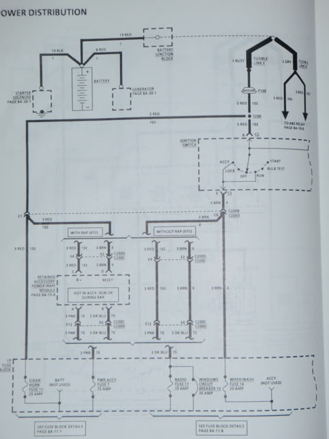
i show incoming power is red, outgoing shows brown as accessory, pink as main ignition wire that is active in run and start position, orange as active in the run position and yellow is active in the start position.
Last edited by craby; 07-31-2010 at 12:25 PM.
#45
07-31-2010, 12:52 PM
Join Date: Mar 2009
Location: Tokeland, Washington
Posts: 21,751
well thats what they are supposed to do with a good switch. it may be that your switch is not letting the juice get to the pink wire in the start position but is getting juice to the yellow for the starter.
#46
07-31-2010, 02:15 PM
on connector "C" (going to pcm) cavity 3, the pink wire is "Ignition Feed" i tested that with a test light and its fine... im assuming thats the same pink wire as you mentioned above that might not be getting power... the only thing i can think of thats wrong is the PCM is bad.. i also tested the 3x crank possition sensor at connector "C" and its good.
what does cavity 27-ignition contol and 28-ignition control bypass, technicaly do?
what does cavity 27-ignition contol and 28-ignition control bypass, technicaly do?
#47
07-31-2010, 03:34 PM
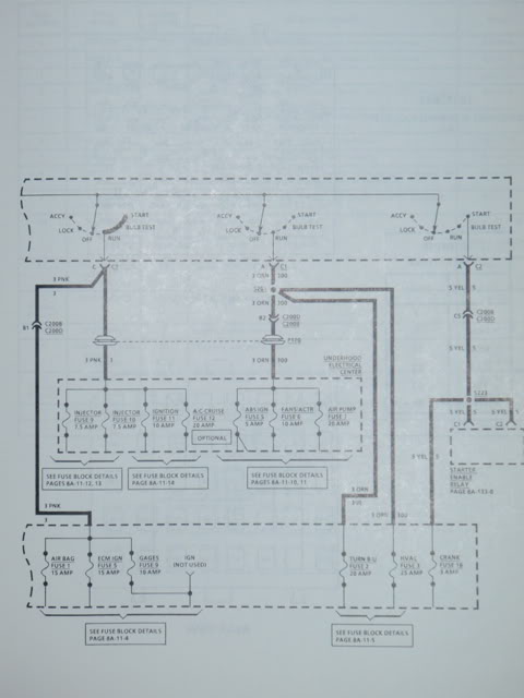
From the schematics, it looks like the ignition control and ignition control bypass is a straight shot from the PCM to the ICM. I can't find a description of what exactly it does. Do you get any voltage readings on pin 27 and 28?
#48
07-31-2010, 03:58 PM
my voltmeter just quit on me, but i have a 6/12 volt test light and it turned on for both of them if i used them as GROUND and other end of test light as POS. to battery.
#49
07-31-2010, 06:57 PM
alright i just got a new volt/ohm meter and her are some thing's i tested
ckt 30to31 (3x ref. low to 3x ref. high) 20k ohm setting=7.92 , 200k ohm setting=25.2 , 2M setting= .133
ckt 17 (pcm ground) one end on positive battery terminal one end on ckt17 showed 12.73V
ckt 3 (ignition feed) with ignition on one end on ckt3 other on battery negative showed 12.51V
ckt 1 (pcm ground) one end on positive battery terminal other on ckt 1 showed 12.71V
*EDIT* and i found the spec's i was looking for on ALLDATA.COM
Vehicle � Specifications � Electrical Specifications � Computers and Control Systems � System Specifications � Part 3 or 3
gonna go through tommorow morning and check everything and see if anythig suspicious shows itself, but so far everything is pointing to bad PCM and just incase it is if i put a new one in from a car (same year,tranny,engine) is there anything special i have to do besides unhook battery take out old pcm install new one?
Last edited by NEW_CAMARO_OWNER; 07-31-2010 at 08:56 PM.
#50
07-31-2010, 09:39 PM
According to what I read on ALLData, The ignition system consists of three ignition coils, and ignition control module, a dual hall effect crankshaft position sensor, and engine crankshaft balancer with interrupter rings attached to the rear, related connecting wires, and the Ignition Control (IC) and fuel metering portion of the ECM. Since you have checked the cranksaft position sensor and changed the ICM, that only
leaves the ECM if the balancer with the interrupter rings is good. But it does say that the ICM has to see the 3x signal from the cranksensor in order to fire the coils. Just one other thing, have you pulled off the connector that screws into the ICM and verified that you didn't accidentially bend any of the pins when installing?
leaves the ECM if the balancer with the interrupter rings is good. But it does say that the ICM has to see the 3x signal from the cranksensor in order to fire the coils. Just one other thing, have you pulled off the connector that screws into the ICM and verified that you didn't accidentially bend any of the pins when installing?
Last edited by osduck5; 07-31-2010 at 09:41 PM.