Manual Brake Installation with Pictures
#1
 11-11-2015, 04:53 AM


I mocked up a prototype manual brake system on a 1991 Firebird. This system requires a 2.0” hole to be drilled in the firewall and a 31/64” hole to be drilled in the pedal.
<a href="http://s724.photobucket.com/user/malibudave/media/IMG_0212.jpg.html" target="_blank"><img src="http://i724.photobucket.com/albums/ww247/malibudave/IMG_0212.jpg" border="0" alt=" photo IMG_0212.jpg"/></a>
The 2.0” hole drilled in the firewall allows the use of the upper two holes that the brake booster bracket utilized and allows a master cylinder to bolt up. This arrangement allows for a 6 to 1 pedal ratio.
<a href="http://s724.photobucket.com/user/malibudave/media/IMG_0213.jpg.html" target="_blank"><img src="http://i724.photobucket.com/albums/ww247/malibudave/IMG_0213.jpg" border="0" alt=" photo IMG_0213.jpg"/></a>
With a true 6 to 1 pedal ratio and using the upper bolt holes in the firewall, you also get good pushrod alignment with the master cylinder piston.
The 31/64” hole, that will be drilled into the brake pedal arm, is good for the ˝” stud/pin to be pressed into the pedal with an optimal interference fit with zero stud/pin play.
To utilize the ˝” stud/pin that is pressed into the brake pedal arm, I made a custom clevis with a ˝” hole for the stud/pin. The clevis is machined to use a 5/16” diameter pushrod with fine threads.
Here are the items used for the pushrod assembly.
<a href="http://s724.photobucket.com/user/malibudave/media/a991a030-bc2a-41eb-a17d-b746fe7845ed.jpg.html" target="_blank"><img src="http://i724.photobucket.com/albums/ww247/malibudave/a991a030-bc2a-41eb-a17d-b746fe7845ed.jpg" border="0" alt=" photo a991a030-bc2a-41eb-a17d-b746fe7845ed.jpg"/></a>
A custom CNC aluminum plate was machined to cover up the original power booster hole and allow GM, Ford, or Mopar style master cylinder to be utilized in the upper holes. A retention cup will also be fabricated and pressed into the plate to retain the pushrod so it doesn't fall out the back of the master cylinder.
Here is the plate bolted to the firewall.
<a href="http://s724.photobucket.com/user/malibudave/media/IMG_0216.jpg.html" target="_blank"><img src="http://i724.photobucket.com/albums/ww247/malibudave/IMG_0216.jpg" border="0" alt=" photo IMG_0216.jpg"/></a>
<a href="http://s724.photobucket.com/user/malibudave/media/IMG_0218.jpg.html" target="_blank"><img src="http://i724.photobucket.com/albums/ww247/malibudave/IMG_0218.jpg" border="0" alt=" photo IMG_0218.jpg"/></a>
<a href="http://s724.photobucket.com/user/malibudave/media/IMG_0217.jpg.html" target="_blank"><img src="http://i724.photobucket.com/albums/ww247/malibudave/IMG_0217.jpg" border="0" alt=" photo IMG_0217.jpg"/></a>
To utilize a Ford or Mopar style master cylinder, the upper passenger side mounting bolt hole in the firewall will have to drilled out to a ˝” in diameter (before the adapter plate is installed) because these master cylinders have a narrower bolt pattern than a GM master cylinder.
Because the third generation F-bodies have significant firewall flex, the prototype manual brake setup utilizes a ˝” thick aluminum plate under the dash between the firewall and the brake pedal assembly. This plate overlaps the contours of the firewall to reduce firewall flex significantly.
I will utilize a 7/8” bore master cylinder because the smaller diameter bore allows for greater pressure in the system and is sized to provide great clamping forces for the stock 2.5” piston calipers.
Here is the system mocked up on the firewall utilizing an old 7/8” bore Mopar style master cylinder I had lying around.
<a href="http://s724.photobucket.com/user/malibudave/media/2015-09/6cc6de62-5dd8-4693-b9d9-2fbdf928423d.jpg.html" target="_blank"><img src="http://i724.photobucket.com/albums/ww247/malibudave/2015-09/6cc6de62-5dd8-4693-b9d9-2fbdf928423d.jpg" border="0" alt=" photo 6cc6de62-5dd8-4693-b9d9-2fbdf928423d.jpg"/></a>
<a href="http://s724.photobucket.com/user/malibudave/media/2015-09/e9cd48b5-7f27-49bb-a473-9cb92634d1ab.jpg.html" target="_blank"><img src="http://i724.photobucket.com/albums/ww247/malibudave/2015-09/e9cd48b5-7f27-49bb-a473-9cb92634d1ab.jpg" border="0" alt=" photo e9cd48b5-7f27-49bb-a473-9cb92634d1ab.jpg"/></a>
<a href="http://s724.photobucket.com/user/malibudave/media/2015-09/127855db-1c6a-4370-b7c9-a79a84578830.jpg.html" target="_blank"><img src="http://i724.photobucket.com/albums/ww247/malibudave/2015-09/127855db-1c6a-4370-b7c9-a79a84578830.jpg" border="0" alt=" photo 127855db-1c6a-4370-b7c9-a79a84578830.jpg"/></a>
<a href="http://s724.photobucket.com/user/malibudave/media/2015-09/b7c203c8-e1e8-426d-859e-5f626b63beee.jpg.html" target="_blank"><img src="http://i724.photobucket.com/albums/ww247/malibudave/2015-09/b7c203c8-e1e8-426d-859e-5f626b63beee.jpg" border="0" alt=" photo b7c203c8-e1e8-426d-859e-5f626b63beee.jpg"/></a>
<a href="http://s724.photobucket.com/user/malibudave/media/2015-09/8e755d00-0230-4c03-87ef-3faf4201919c.jpg.html" target="_blank"><img src="http://i724.photobucket.com/albums/ww247/malibudave/2015-09/8e755d00-0230-4c03-87ef-3faf4201919c.jpg" border="0" alt=" photo 8e755d00-0230-4c03-87ef-3faf4201919c.jpg"/></a>
<a href="http://s724.photobucket.com/user/malibudave/media/2015-09/AA963A67-FE17-4EAA-93A8-A777EC48EBCA.jpg.html" target="_blank"><img src="http://i724.photobucket.com/albums/ww247/malibudave/2015-09/AA963A67-FE17-4EAA-93A8-A777EC48EBCA.jpg" border="0" alt=" photo AA963A67-FE17-4EAA-93A8-A777EC48EBCA.jpg"/></a>
From the factory, the stock calipers are LOW drag. LOW drag calipers will require a step bore master cylinder. Step bore master cylinders have two bores. The secondary, pressure bore is 24mm, which in my opinion, is too large to operate manual brakes. Also, the master cylinder does not have a mechanism to retain the pushrod. If the pushrod falls away from the master cylinder piston, the car will loose all its brakes.
NON low drag (normal) calipers are available that will bolt in to systems utilizing the stock 10.5" front brakes. I like the Centric brand rebuilt units. The part numbers are 14162066 and 14162065 (left and right hand side) and have the stock 2.5” piston diameters. AFCO just released some brand new cast iron castings with stock 2.5” bore. The part numbers for these are 6635003 and 6635004 for left and right hand side calipers.
The ports on the Mopar style master cylinder are 3/8-24 and will utilize this size line to mate up to the stock prop valve. I just need to figure out the prop valve inlet thread size to see if there are any adapters to mate to the 3/8-24 line fittings.
<a href="http://s724.photobucket.com/user/malibudave/media/IMG_0212.jpg.html" target="_blank"><img src="http://i724.photobucket.com/albums/ww247/malibudave/IMG_0212.jpg" border="0" alt=" photo IMG_0212.jpg"/></a>
The 2.0” hole drilled in the firewall allows the use of the upper two holes that the brake booster bracket utilized and allows a master cylinder to bolt up. This arrangement allows for a 6 to 1 pedal ratio.
<a href="http://s724.photobucket.com/user/malibudave/media/IMG_0213.jpg.html" target="_blank"><img src="http://i724.photobucket.com/albums/ww247/malibudave/IMG_0213.jpg" border="0" alt=" photo IMG_0213.jpg"/></a>
With a true 6 to 1 pedal ratio and using the upper bolt holes in the firewall, you also get good pushrod alignment with the master cylinder piston.
The 31/64” hole, that will be drilled into the brake pedal arm, is good for the ˝” stud/pin to be pressed into the pedal with an optimal interference fit with zero stud/pin play.
To utilize the ˝” stud/pin that is pressed into the brake pedal arm, I made a custom clevis with a ˝” hole for the stud/pin. The clevis is machined to use a 5/16” diameter pushrod with fine threads.
Here are the items used for the pushrod assembly.
<a href="http://s724.photobucket.com/user/malibudave/media/a991a030-bc2a-41eb-a17d-b746fe7845ed.jpg.html" target="_blank"><img src="http://i724.photobucket.com/albums/ww247/malibudave/a991a030-bc2a-41eb-a17d-b746fe7845ed.jpg" border="0" alt=" photo a991a030-bc2a-41eb-a17d-b746fe7845ed.jpg"/></a>
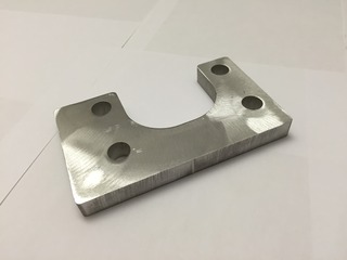
A custom CNC aluminum plate was machined to cover up the original power booster hole and allow GM, Ford, or Mopar style master cylinder to be utilized in the upper holes. A retention cup will also be fabricated and pressed into the plate to retain the pushrod so it doesn't fall out the back of the master cylinder.
Here is the plate bolted to the firewall.
<a href="http://s724.photobucket.com/user/malibudave/media/IMG_0216.jpg.html" target="_blank"><img src="http://i724.photobucket.com/albums/ww247/malibudave/IMG_0216.jpg" border="0" alt=" photo IMG_0216.jpg"/></a>
<a href="http://s724.photobucket.com/user/malibudave/media/IMG_0218.jpg.html" target="_blank"><img src="http://i724.photobucket.com/albums/ww247/malibudave/IMG_0218.jpg" border="0" alt=" photo IMG_0218.jpg"/></a>
<a href="http://s724.photobucket.com/user/malibudave/media/IMG_0217.jpg.html" target="_blank"><img src="http://i724.photobucket.com/albums/ww247/malibudave/IMG_0217.jpg" border="0" alt=" photo IMG_0217.jpg"/></a>
To utilize a Ford or Mopar style master cylinder, the upper passenger side mounting bolt hole in the firewall will have to drilled out to a ˝” in diameter (before the adapter plate is installed) because these master cylinders have a narrower bolt pattern than a GM master cylinder.
Because the third generation F-bodies have significant firewall flex, the prototype manual brake setup utilizes a ˝” thick aluminum plate under the dash between the firewall and the brake pedal assembly. This plate overlaps the contours of the firewall to reduce firewall flex significantly.
I will utilize a 7/8” bore master cylinder because the smaller diameter bore allows for greater pressure in the system and is sized to provide great clamping forces for the stock 2.5” piston calipers.
Here is the system mocked up on the firewall utilizing an old 7/8” bore Mopar style master cylinder I had lying around.
<a href="http://s724.photobucket.com/user/malibudave/media/2015-09/6cc6de62-5dd8-4693-b9d9-2fbdf928423d.jpg.html" target="_blank"><img src="http://i724.photobucket.com/albums/ww247/malibudave/2015-09/6cc6de62-5dd8-4693-b9d9-2fbdf928423d.jpg" border="0" alt=" photo 6cc6de62-5dd8-4693-b9d9-2fbdf928423d.jpg"/></a>
<a href="http://s724.photobucket.com/user/malibudave/media/2015-09/e9cd48b5-7f27-49bb-a473-9cb92634d1ab.jpg.html" target="_blank"><img src="http://i724.photobucket.com/albums/ww247/malibudave/2015-09/e9cd48b5-7f27-49bb-a473-9cb92634d1ab.jpg" border="0" alt=" photo e9cd48b5-7f27-49bb-a473-9cb92634d1ab.jpg"/></a>
<a href="http://s724.photobucket.com/user/malibudave/media/2015-09/127855db-1c6a-4370-b7c9-a79a84578830.jpg.html" target="_blank"><img src="http://i724.photobucket.com/albums/ww247/malibudave/2015-09/127855db-1c6a-4370-b7c9-a79a84578830.jpg" border="0" alt=" photo 127855db-1c6a-4370-b7c9-a79a84578830.jpg"/></a>
<a href="http://s724.photobucket.com/user/malibudave/media/2015-09/b7c203c8-e1e8-426d-859e-5f626b63beee.jpg.html" target="_blank"><img src="http://i724.photobucket.com/albums/ww247/malibudave/2015-09/b7c203c8-e1e8-426d-859e-5f626b63beee.jpg" border="0" alt=" photo b7c203c8-e1e8-426d-859e-5f626b63beee.jpg"/></a>
<a href="http://s724.photobucket.com/user/malibudave/media/2015-09/8e755d00-0230-4c03-87ef-3faf4201919c.jpg.html" target="_blank"><img src="http://i724.photobucket.com/albums/ww247/malibudave/2015-09/8e755d00-0230-4c03-87ef-3faf4201919c.jpg" border="0" alt=" photo 8e755d00-0230-4c03-87ef-3faf4201919c.jpg"/></a>
<a href="http://s724.photobucket.com/user/malibudave/media/2015-09/AA963A67-FE17-4EAA-93A8-A777EC48EBCA.jpg.html" target="_blank"><img src="http://i724.photobucket.com/albums/ww247/malibudave/2015-09/AA963A67-FE17-4EAA-93A8-A777EC48EBCA.jpg" border="0" alt=" photo AA963A67-FE17-4EAA-93A8-A777EC48EBCA.jpg"/></a>
From the factory, the stock calipers are LOW drag. LOW drag calipers will require a step bore master cylinder. Step bore master cylinders have two bores. The secondary, pressure bore is 24mm, which in my opinion, is too large to operate manual brakes. Also, the master cylinder does not have a mechanism to retain the pushrod. If the pushrod falls away from the master cylinder piston, the car will loose all its brakes.
NON low drag (normal) calipers are available that will bolt in to systems utilizing the stock 10.5" front brakes. I like the Centric brand rebuilt units. The part numbers are 14162066 and 14162065 (left and right hand side) and have the stock 2.5” piston diameters. AFCO just released some brand new cast iron castings with stock 2.5” bore. The part numbers for these are 6635003 and 6635004 for left and right hand side calipers.
The ports on the Mopar style master cylinder are 3/8-24 and will utilize this size line to mate up to the stock prop valve. I just need to figure out the prop valve inlet thread size to see if there are any adapters to mate to the 3/8-24 line fittings.
#2
11-11-2015, 04:53 AM
I did some measuring of the brake pedal assembly to find out what the stock power assist, vacuum booster pedal ratio would be. I also did the calculations of the manual brake system output at the master cylinder using different pedal ratios and master cylinder bore sizes.
Stock pedal length from center of pivot point to center of pedal pad is 12.0”
BOOSTED PEDAL RATIO
Distance from center of pivot point to center of power booster pin/stud location is 3.75”
12 ÷ 3.75 = 3.2 to 1 pedal ratio
MANUAL BRAKE PEDAL RATIO
On the F-body pedal, I moved the pin/stud location up on the pedal where it was 2.0” down from the pivot point.
12 ÷ 2 = 6 to 1 pedal ratio
I wanted to make sure my manual brakes have enough pedal ratio to create the greatest amount of leverage with roughly 1.0” of master cylinder piston travel. In this case, the 6 to 1 ratio worked out to be 1.0” (give or take a 1/16 of an inch).
After reading some of the other posts on their manual brake conversion, they moved the stud up 1.0” from the power boosted pin location.
12 ÷ 2.75 = 4.4 to 1 pedal ratio
For most brake systems, a 7/8” bore master cylinder will work well and create greater pressure than the larger 1.03” bore master cylinders.
Area of master cylinder bore:
• 7/8” bore master cylinder – 0.601 square inches
• 24mm bore master cylinder – 0.701 square inches
• 1-1/32” bore master cylinder – 0.836 square inches
If 100 pounds of pressure is applied to the brake pedal and a 6 to 1 pedal ratio:
• 7/8” bore master cylinder will create 998 psi of manual pressure
• 24mm bore master cylinder will create 886 psi of manual pressure
• 1-1/32” bore master cylinder will create 720 psi of manual pressure
If 100 pounds of pressure is applied to the brake pedal and a 4.4 to 1 pedal ratio:
• 7/8” bore master cylinder will create 732 psi of manual pressure
• 24mm bore master cylinder will create 628 psi of manual pressure
• 1-1/32” bore master cylinder will create 528 psi of manual pressure
VACUUM BOOSTED BRAKES PSI
If 100 pounds of pressure is applied to the brake pedal and a 3.2 to 1 pedal ratio:
• 24mm (stock size) secondary bore master cylinder will create 456 psi of manual pressure
• Area of a 9.0” dual diaphragm vacuum booster – 127.12 square inches
• 18 in Hg of vacuum converted to psi – 8.8 psi
• 127.12 square inches multiplied by 8.8 psi equals 1119 psi of vacuum boosted pressure
• 456 psi of manual pressure plus 1119 psi of vacuum boosted pressure is 1575 psi of pressure
Hopefully the vacuum boosted pressure is accurate. I am assuming that both diaphragms have the same area.
#3
11-11-2015, 04:54 AM
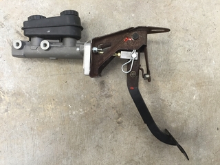
Here is the brake pedal assembly mocked up with the manual brake setup off the car. I wanted to make sure that here was no contact with the pushrod retention cup. The pushrod retention cup makes sure that the pushrod does not fall away from the back of the master cylinder piston. If the pushrod falls away from the back of the master cylinder piston, you will have ZERO brakes. For this mock up, the bottom stainless steel button head bolts for the adapter plate where not needed.
From left to right:
7/8" Bore Master Cylinder
1/8" Thick Aluminum Adapter Plate with Pushrod Retention Cup that installs in engine bay
1/2" Thick Aluminum Firewall Brace that will install under dash
Stock Brake pedal Assembly Bracket.
From left to right:
7/8" Bore Master Cylinder
1/8" Thick Aluminum Adapter Plate with Pushrod Retention Cup that installs in engine bay
1/2" Thick Aluminum Firewall Brace that will install under dash
Stock Brake pedal Assembly Bracket.

#4
11-11-2015, 04:55 AM
Stock third generation (1982-1992) F-body front 10.5” front brake rotors and front brake calipers interchange with:
• 1978-1988 RWD A/G-body Cars (1978 and some 1979 g-body rotors used smaller outer wheel bearings and will not interchange with newer models)
• 1982-2003 RWD S10 Trucks and SUVs with 10.5” rotors
From 1978 -1981 A/G-body cars used normal front brake calipers and a 7/8” strait bore (normal) master cylinder in factory manual brake equipped cars. Vacuum assisted cars used a 24mm strait bore (normal) master cylinder. The manual brake equipped vehicles came with a 6 to 1 pedal ratio.
After 1982, there were no manual brake equipped g-bodies from the factory. After 1982, the brake calipers on third generation f-bodies, g-bodies, and S10 trucks/SUVs where manufactured with low drag seals and were commonly called LOW drag calipers. These LOW drag calipers were designed with a seal with a beveled edge. This beveled edged seal “pulled” back the caliper piston further into the brake caliper bore and increase the amount of space between the rotor and the brake pad. This was an effort to increase gas mileage.
Because the LOW drag caliper “pulled” the pads farther away from the rotor, more brake fluid volume is needed to get the pads back up against the rotor. To remedy this, GM engineers used a step bore master cylinder which had two different size bores. The primary, larger bore to move the volume and a smaller, secondary bore to create pressure. When the brake pedal is pressed, the larger bore moved the volume of fluid needed to get the pads back up against the rotor without additional pedal travel. Once a certain pressure is reached inside the master cylinder, an internal bypass valve would activate, and the smaller, secondary bore would allow sufficient pressure to clamp the pads against the rotors and stop the car.
First generation S10 trucks came from the factory with manual brakes, LOW drag calipers, and a step bore master cylinder. The step bore master cylinder’s smaller secondary bore of the manual brake equipped master cylinder was 24mm.
In my opinion, you do not want to try and make a step bore master cylinder work with any manual brake setup. The step bore master cylinder is:
• more complicated to bleed because of the internal bypass valve
• secondary, 24mm bore is too large for the stock size of the calipers being used to create enough pressure
• the internal bypass valve may and can malfunction
• no way to retain the pushrod against the back of the master cylinder piston
• New step bore master cylinders are cast iron
• Step bore master cylinders are physically larger than most other master cylinders
A good, simple matched system for manual brakes would be:
• Stock size (2.5” piston) front calipers (new and rebuilt units are most likely normal, NON low drag)
• A normal, 7/8” strait bore master cylinder
• 6 to 1 pedal ratio.
#5
11-11-2015, 04:55 AM
The 7/8" master cylinder that I will be using has 3/8-24 inch outlets. These outlets will have to mate up to 12x1.5 inlet on the proportioning valve for the rear brakes (front port on the proportioning valve) and 11x1.5 inlet on the proportioning valve for the front brakes (rear inlet port on the proportioning valve).
For the rear brake lines running from the front port of the master cylinder to the front port of the proportioning valve, use Edelmann part number 265000 installed in the front inlet port of the proportioning valve. I will then bend up a 20" hard line of 3/16" diameter tubing with 3/8-24 inch fittings. The hard line is Edelmann Part # 320PVF
For the front brake lines running from the rear port of the master cylinder to the rear port of the proportioning valve, use Edelmann part number 264000 installed in the rear inlet port of the proportioning valve. I will then bend up a 20" hard line of 3/16" diameter tubing with 3/8-24 inch fittings. The hard line is Edelmann Part # 320PVF
Here are the part numbers you need to mate the master cylinder with 3/8-24 inch outlets to a proportioning valve with 12x1 and 11x1.5 inlet sizes.
2 each of Edelmann Part # 320PVF - 20 inch long, 3/16 inch outside diameter tube with 3/8-24 inch fittings.
Edelmann Part # 265000 - 12x1 bubble flare male to 3/8-24-24 inch inverted flare female.
Edelmann Part # 264000 - 11x1.5 bubble flare male to 3/8-24 inch inverted flare female.
#6
11-11-2015, 04:56 AM
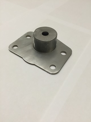
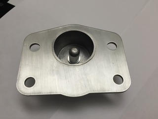
Here are different views the finished manual brake adapter plate if looking at it from the engine bay side. A pushrod retention cup is added to make sure the pushrod does not fall away from the back of the master cylinder piston if brake fluid pressure is lost. The “bump” at the bottom of the adapter plate is to completely cover the hole that the brake booster bracket used.
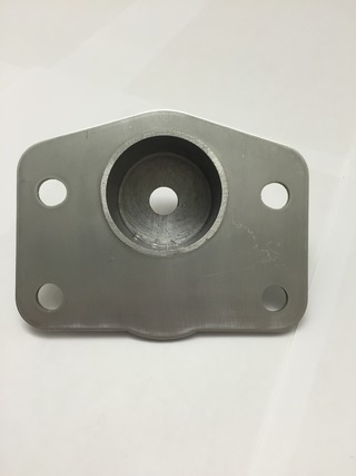
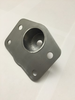
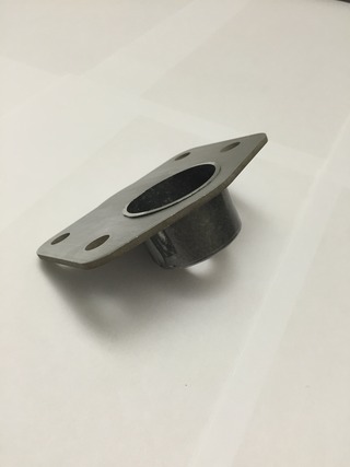
The below picture is the backside of the adapter plate that will mount against the firewall. The pushrod retention cup will install through the 2.0" hole drilled in the firewall.
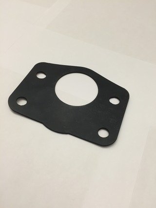
The below picture is the matching gasket for the manual brake adapter plate. The gasket will be sandwiched between the firewall after it is slid over the top of the retention cup in the above picture.
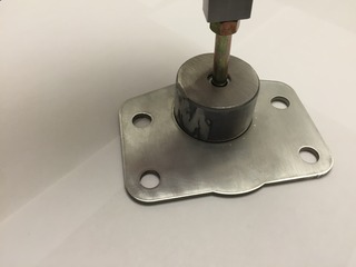
The below picture is the manual brake adjustable pushrod installed in the retention cup. The pushrod has provisions to keep it captured inside the pushrod retention cup. You would see this view from the engine bay before the master cylinder is installed and after you installed your adjustable pushrod assembly to the brake pedal arm.
The below picture is the manual brake adjustable pushrod installed in the cup. You would see this view from under the dash after the adjustable pushrod assembly is installed on the brake pedal arm.
The below picture is the 1/2" thick aluminum firewall brace. It is installed under the dash, between the firewall and the brake pedal assembly bracket. The firewall brace is extended toward the driver side and bottom do take advantage of the stamped portion of the firewall. It significantly reduces firewall flex.


The below picture is the backside of the adapter plate that will mount against the firewall. The pushrod retention cup will install through the 2.0" hole drilled in the firewall.

The below picture is the matching gasket for the manual brake adapter plate. The gasket will be sandwiched between the firewall after it is slid over the top of the retention cup in the above picture.

The below picture is the manual brake adjustable pushrod installed in the retention cup. The pushrod has provisions to keep it captured inside the pushrod retention cup. You would see this view from the engine bay before the master cylinder is installed and after you installed your adjustable pushrod assembly to the brake pedal arm.

The below picture is the manual brake adjustable pushrod installed in the cup. You would see this view from under the dash after the adjustable pushrod assembly is installed on the brake pedal arm.

The below picture is the 1/2" thick aluminum firewall brace. It is installed under the dash, between the firewall and the brake pedal assembly bracket. The firewall brace is extended toward the driver side and bottom do take advantage of the stamped portion of the firewall. It significantly reduces firewall flex.

#7
02-18-2016, 05:38 PM
Below is an analysis using the Brake Torque Calculator found on Pro-Touring.com. This calculator will give you an idea of what brake torque is for a certain front and rear setups. I am just going to show the changes from the stock, third generation front f-body brake system and compare them to a stock LS1 Camaro brake swap, a LS1 Camaro brake swap with Corvette calipers
Page 7, Post #140
Brake sizing and selection tutorial featuring Ron Sutton and Tobin of KORE3 - Page 7
This entire post is a really good read if you are interested about brakes.
Here are the inputs that are the same for ALL different types of brake systems shown below.
• 6 to 1 pedal ratio
• 26” tall tire
• 100 ft/lb pedal pressure
• Manual Brakes – NO POWER ASSIST
• Pad Coefficient of Friction - .45
• Use of stock type (tandem) master cylinder
__________________________________________________ __
Stock G-body/S10/3rd Generation F-body Front Brake System
• Rotor Diameter – 10.5”
• 7/8” Bore Master Cylinder Area - .601 sq-in
• Line Pressure – 998 psi
• Front Caliper Piston Area – 4.909 sq-in
• Front Clamping Pressure – 4899 pounds
• Front Rotor Torque – 964 ft/lb
• Tire Forces – 890 lb
__________________________________________________ __
Stock LS1 Camaro/Firebird Front Brake System
• Rotor Diameter – 12”
• 7/8” Bore Master Cylinder Area - .601 sq-in
• Line Pressure – 998 psi
• Front Caliper Piston Area – 4.931 sq-in
• Front Clamping Pressure – 4921 pounds
• Front Rotor Torque – 1107 ft/lb
• Tire Forces – 1022 lb
__________________________________________________ __
Stock LS1 Camaro/Firebird Front Brake System with Corvette Calipers with 7/8” bore master cylinder
• Rotor Diameter – 12”
• 7/8” Bore Master Cylinder Area - .601 sq-in
• Line Pressure – 998 psi
• Front Caliper Piston Area – 3.994 sq-in
• Front Clamping Pressure – 3986 pounds
• Front Rotor Torque – 897 ft/lb
• Tire Forces – 828 lb
Stock LS1 Camaro/Firebird Front Brake System with Corvette Calipers with 21mm bore master cylinder
• Rotor Diameter – 12”
• 21mm Bore Master Cylinder Area - .537 sq-in
• Line Pressure – 1117 psi
• Front Caliper Piston Area – 3.994 sq-in
• Front Clamping Pressure – 4461 pounds
• Front Rotor Torque – 1004 ft/lb
• Tire Forces – 927 lb
Rating from best to worst:
1. LS1 Camaro / Firebird stock front brakes with 7/8" bore master cylinder.
2. LS1 Camaro / Firebird front brakes with Corvette brake calipers and a 21mm bore master cylinder. NOTE: A 21mm master cylinders are fairly rare and hard to find.
3. Stock g-body/S10/3rd Generation F-body stock front brake system with 7/8" bore master cylinder.
4. LS1 Camaro / Firebird front brakes with Corvette brake calipers and a 7/8” bore master cylinder.

Thread
Thread Starter
Forum
Replies
Last Post