Nitrous wiring diagram
#1
 05-26-2008, 05:47 PM


These are the schematics I made to follow when wiring up my kit. Since you end up with lots and lots off wire you had better have a game plan before tearing into your dash.
The Relay
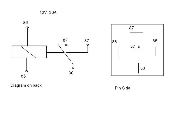
Quite possibly one of the most confusing parts of the install (if you arent familiar with wiring that is). A relay is a device that uses one current to activate another current. Your relay will probably look like what is on the right. Left is a diagram (meaningless unless you know what you're looking at) that will appear somewhere on the 5 pin relay. The picture on the right shows all 5 pins as they would appear (the pins are the short lines, and in reality look a little like a prong for any standard electrical plug)
The relay has 2 sides to it, the power side, and the activated side (or at least thats the terminology I will use). Pins 85 and 86 are on the "Power Side" of the relay, and these pins are connected to an electro magnet. Directions will be given on the package as to which pin should be pos or neg, although connecting them in either direction should produce a magnetic field, although some use internal resistors and should be wired with the correct flow direction.
Pins 87, 87a, and 30 are the "activated" side of the relay. This circuit will utilize pin 30 and ONE of the other pins. Under normal conditions pin 87a is connected to 30 at all times. That is, when the relay is NOT powered, wires connected to 87a and 30 form a closed circuit loop. However, once the magnet is turned on by powering the relay, a metal lever is pulled over from 87a to 87. Pin 87 is now the closed loop. In this way, you can use a relay to ADD power or to TAKE AWAY power from a circuit.
But this is nitrous, so we want to ACTIVATE it with a switch, not deactivate it. Therefore use pin 87 and 30 for wiring your solenoids.
Wiring The Solenoids
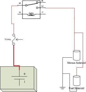
As previously stated, the solenoids exist on their own circuit. Now, modifications to this can be made by personal preference. i.e. you may add individual switches or the WOT switch into this circuit as a failsafe if the relay fails. I have had 1 relay fail on me, but it happened when I mounted it in a bad location and crushed it when I closed my hood, the result off which was smashing the pin 30 lever into pin 87 and completing the circuit. Other than physical damage, I wouldnt expect your relay to fail.
In the diagram above, the pin marked 5 is 30, and the pin marked 3 is 87. The unconnected pins are 85 and 86. The only other note about this diagram is that when connecting the solenoids to a single circuit like this there is a possibility that one may fail while the other works. By connecting the wire from the relay to the positive on one solenoid, then connecting the negative of that solenoid to the positive of the other, then grounding out solenoid 2, you will have the same effect of a burnt out christmas light. If one doesnt go, nothing goes. This is just another precaution you can take.
The Master Switch and Window Switch
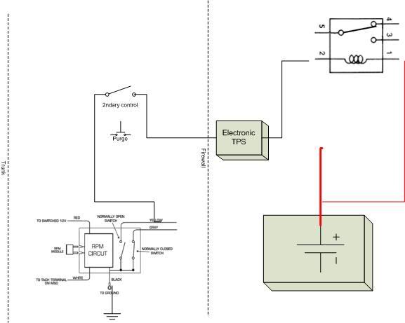
This diagram shows the innards of an MSD window switch. The window switch is essentially another electromagnet, however it only produces its magnetic field at certain rpm specified by the "RPM Circut".
Again
The Relay
Quite possibly one of the most confusing parts of the install (if you arent familiar with wiring that is). A relay is a device that uses one current to activate another current. Your relay will probably look like what is on the right. Left is a diagram (meaningless unless you know what you're looking at) that will appear somewhere on the 5 pin relay. The picture on the right shows all 5 pins as they would appear (the pins are the short lines, and in reality look a little like a prong for any standard electrical plug)
The relay has 2 sides to it, the power side, and the activated side (or at least thats the terminology I will use). Pins 85 and 86 are on the "Power Side" of the relay, and these pins are connected to an electro magnet. Directions will be given on the package as to which pin should be pos or neg, although connecting them in either direction should produce a magnetic field, although some use internal resistors and should be wired with the correct flow direction.
Pins 87, 87a, and 30 are the "activated" side of the relay. This circuit will utilize pin 30 and ONE of the other pins. Under normal conditions pin 87a is connected to 30 at all times. That is, when the relay is NOT powered, wires connected to 87a and 30 form a closed circuit loop. However, once the magnet is turned on by powering the relay, a metal lever is pulled over from 87a to 87. Pin 87 is now the closed loop. In this way, you can use a relay to ADD power or to TAKE AWAY power from a circuit.
But this is nitrous, so we want to ACTIVATE it with a switch, not deactivate it. Therefore use pin 87 and 30 for wiring your solenoids.
Wiring The Solenoids
As previously stated, the solenoids exist on their own circuit. Now, modifications to this can be made by personal preference. i.e. you may add individual switches or the WOT switch into this circuit as a failsafe if the relay fails. I have had 1 relay fail on me, but it happened when I mounted it in a bad location and crushed it when I closed my hood, the result off which was smashing the pin 30 lever into pin 87 and completing the circuit. Other than physical damage, I wouldnt expect your relay to fail.
In the diagram above, the pin marked 5 is 30, and the pin marked 3 is 87. The unconnected pins are 85 and 86. The only other note about this diagram is that when connecting the solenoids to a single circuit like this there is a possibility that one may fail while the other works. By connecting the wire from the relay to the positive on one solenoid, then connecting the negative of that solenoid to the positive of the other, then grounding out solenoid 2, you will have the same effect of a burnt out christmas light. If one doesnt go, nothing goes. This is just another precaution you can take.
The Master Switch and Window Switch
This diagram shows the innards of an MSD window switch. The window switch is essentially another electromagnet, however it only produces its magnetic field at certain rpm specified by the "RPM Circut".
Again

#3
06-25-2009, 10:01 PM

Join Date: May 2007
Location: Fort Brag NC (no longer in iraq)
Posts: 2,200
Some times on a very basic system there are no needs for relays. An example of this would be with out saftys of course. But would be perfect for a small dry shot, intercooler spray, ect, ect.
Very good read spec. Maybe when you have some time build one for a bottle heater and add fuel and nitrous safty switchs
On a side note some nitrous guys love building over complicated wiring harness when building nitrous kits. Wiring every thing into one big harness (bottle heater, purge, arming switch, nitrous control box, engine fan, etc, etc) When doing this it will be tied in by relays. This can make for a clean set up when done right. HOWEVER make sure you know or the shot knows what they are doing if you or they attempt to run every thing as one unit. The reason being if you have a crash any wear in the system the hole system may crash resulting in a very bad day checking relays and looking for burnt wires.
It happend too me. Know i keep my systems as simple as possible and run them as single units. For example my bottle heater and soleniods are in no way connected except at the power source.
#4
07-07-2009, 01:13 PM
i actually have a master diagram somewhere w/ the bottle hearter, fpss, and other goodies all tied in.... ill have to go back and find it
#6
07-07-2009, 01:17 PM
damn... I dont know why its so small.... and i dont have access to the software that i made it on anymore
#7
10-12-2009, 12:44 PM

Very informative thread. Thank you
Everyone should read this: The truth about Superchargers and the 4 types that exist
Everyone should read this: The truth about Superchargers and the 4 types that exist


Thread
Thread Starter
Forum
Replies
Last Post