Voltage Regulator diode? / Wire harness
#1
 01-24-2011, 08:06 AM


One step forward, two steps back...
I actually have two questions if anyone can help.
Ok, so I got most of the wiring harness routed to the front headlights, marker lamps etc, but where is the harness supposed to be routed to cross over from the drivers side to the passenger side? I put it in front of the radiator, but for the life of me I can't remember if this is correct, and if so, where do I tuck it in at, or secure it to so it's not just flopping between the grill and the radiator?
Alright, Voltage regulator. So I was peeling off "black tape" to the wires that connect to the VR and on the second lead to the Voltage Regulator I find what I'm thinking is a diode hap hazardly spliced into the circuit. I have no idea why, or if this is needed. Long story short, I decided to solder it in and then shrink wrap it to make it look pretty, except I broke it.
So, do I need this and can anybody guess why this was put there in the first place?
Thanks in advanced!
Confused.
Last edited by StoveBolts; 01-24-2011 at 08:09 AM.
#2
01-24-2011, 08:49 AM
If you have an AIM, look on UPC12 A8. It has a very clear picture of the harness routing to the headlights. RS models and convertibles have minor differences in teh actual routing...look at UPC Z22 A11 and A13.
Let me know if you don't have AIM and I'll try to get a copy of the pages.
As far as the diode is concerned...I haven't looked the schematic that closely....but I do not recall seeing a diode. Can you give more detail? What color of wire is it in?
Does your car have the original (i.e. correct) voltage regulator and generator?
Vic
#3
01-24-2011, 10:20 AM
If you have an AIM, look on UPC12 A8. It has a very clear picture of the harness routing to the headlights. RS models and convertibles have minor differences in teh actual routing...look at UPC Z22 A11 and A13.
Let me know if you don't have AIM and I'll try to get a copy of the pages.
As far as the diode is concerned...I haven't looked the schematic that closely....but I do not recall seeing a diode. Can you give more detail? What color of wire is it in?
Does your car have the original (i.e. correct) voltage regulator and generator?
Vic
Let me know if you don't have AIM and I'll try to get a copy of the pages.
As far as the diode is concerned...I haven't looked the schematic that closely....but I do not recall seeing a diode. Can you give more detail? What color of wire is it in?
Does your car have the original (i.e. correct) voltage regulator and generator?
Vic
I have an aftermarket 100 amp alternator that can be used as a "single wire" or 2 wire that can ran through the VR. I wired it to run through the VR.
I believe the VR is original.
I was looking online and found this about the diode. I suppose this explains it.
http://www.msdignition.com/page.aspx?id=3296
I'm telling you, they previous owner was a hack... What a mess.
From the positive battery lead, there is a 10 guage wire that goes to a factory Junction box just behind the battery, and then from there, it routes across the front of the car to a make shift junction where the previous owner put eye connectors on 4 wires and bolted them together, then wrapped the whole blob in electrical tape. What a mess. I'll see if I can take some pictures tonight and post.
Anyway, from what I remember, one wire went to the VR and the other wire went to the horn relay. I'll try to draw it out.
From Battery -----------||---------Firewall
Horn Relay--------------||---------Voltage Regulator
Anyway, I don't think 4 eye hooks with a bolt wrapped in a blob of tape holding all four wires together is 'correct' and I'm thinking about going to Radio shack for a proper junction box I can mount on the core support. Any ideas or would my idea be ok?
One other question, and I found an AIM on the front electrical, but my front parking lights won't work. It looks like they tie into the side marker lights (they work). According to the schmatic, it looks like the parking lights have a black and brown wire and the diagram show a seperate ground (I'm thinking like the rear lights where it uses the housing as a ground. How in the world does the parking lights housing ground when it's in a plastic grill? I know I'm missing something. BTW, my painter did me a favor and put my new grill in. Did he miss a ground strap or something?
Last edited by StoveBolts; 01-24-2011 at 10:31 AM. Reason: edited for clarity?...

#6
01-24-2011, 12:05 PM
Jeff,
things become much more complex when changes are made from the original system. It would seem that you also have a different ignition system ...as the link you gave gave is for an MSD system. I will let others comment who may have the same set up....burnt68?
So to try to answer your original question....I would have to say...if it works....then just clean up the mess and leave it in the circuit.
Now as far as the parking lights and markers are concerned. The schematic actually shows that there is in fact a wire coming from each housing. It runs from each unit and goes to a ground point....it does not specify where the wire ground is taken from. (Of course any good ground will do but you may want to ask someone to trace theirs out for correctness. (Mine is an RS so it's different).
I hope this has been of some help.
Vic
#7
01-24-2011, 01:04 PM
Thanks Vic, I appreciate your help.
Burnt, a picture is worth a thousand words. Thanks, it really helps.
Ok, so I see your VR mouts directly above the horn relay and I also noticed two fusible links. Come to think of it, I don't have a fusible link.
Looking at your picture, you basically have 3 hots. The two with the fusible links, and the second one coming off the horn relay. Do you know where these three wires are joined together? (See my makeshift diagram above).
Also, while browsing Ricks earlier I noticed rubber isolators for the VR where it mounts to the Rad support. Isolators Burnt that I see you have, but mine never has. How important are those? I also noticed a makeshift ground on my VR that I thought was odd being the VR was bolted directly to the Rad support... Suppose I don't need that. Things that make ya go hmmmm...
Anyway Rad, is there anyway I could talk you into getting me a picture how / where they clipped that harness to the Rad support?
As far as the diode, I suppose I'll just leave it out and if the car don't turn off when I turn it off maybe I'll know why. But then again, the diode was on the 2nd lead, not the 4th lead like MSD says. hmmmm.
#8
01-24-2011, 07:18 PM

Isolators, electrically speaking, are used to keep electrical separation between two conductors. It sounds like your electrical system has been heavily modified and changes to it's present form, without knowing exactly what you are doing in this area, could cause some serious problems. I am fairly certain that most people on this web site can attest to strange electrical phenomenon due to grounding issues. Are you having any electrical issues, or are you just cleaning things up a bit?
#9
01-25-2011, 07:22 AM
Hi brunk5
Well... the car's been sitting kinda in pieces since late summer of 2003. Just before I tore it apart I was having some very odd electrical issues with the lights and I've deduced that it was the head light switch. I just picked up a new switch ($12) from Advanced Auto last night and will install it sometime soon so that should confirm it. And yes, I'm trying to clean it up a bit. When you see electrical tape blobs here and there, well... I've put so much work into this car I want it to be as nice as I can within my very limited budget.
anyway, I took some pictures last night and will post them in my next post.
#10
01-25-2011, 07:26 AM
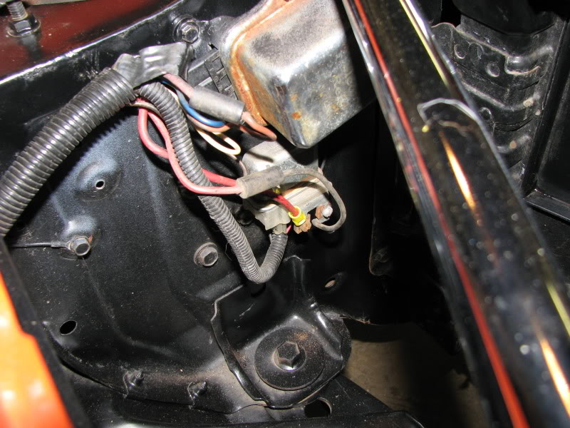
Here is the Rad support. You can see I started casing the wires in shrink tubing.
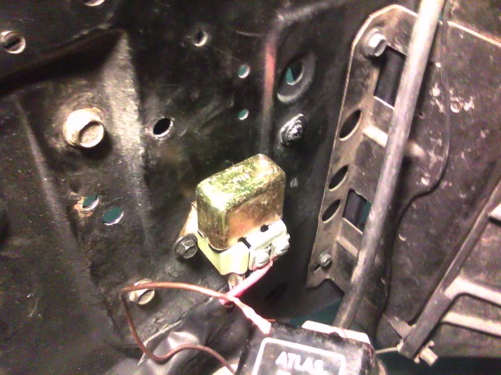
Here is the VR. They had a diode twisted and spliced into the 2nd wire that now has a butt connector.
Surprise!
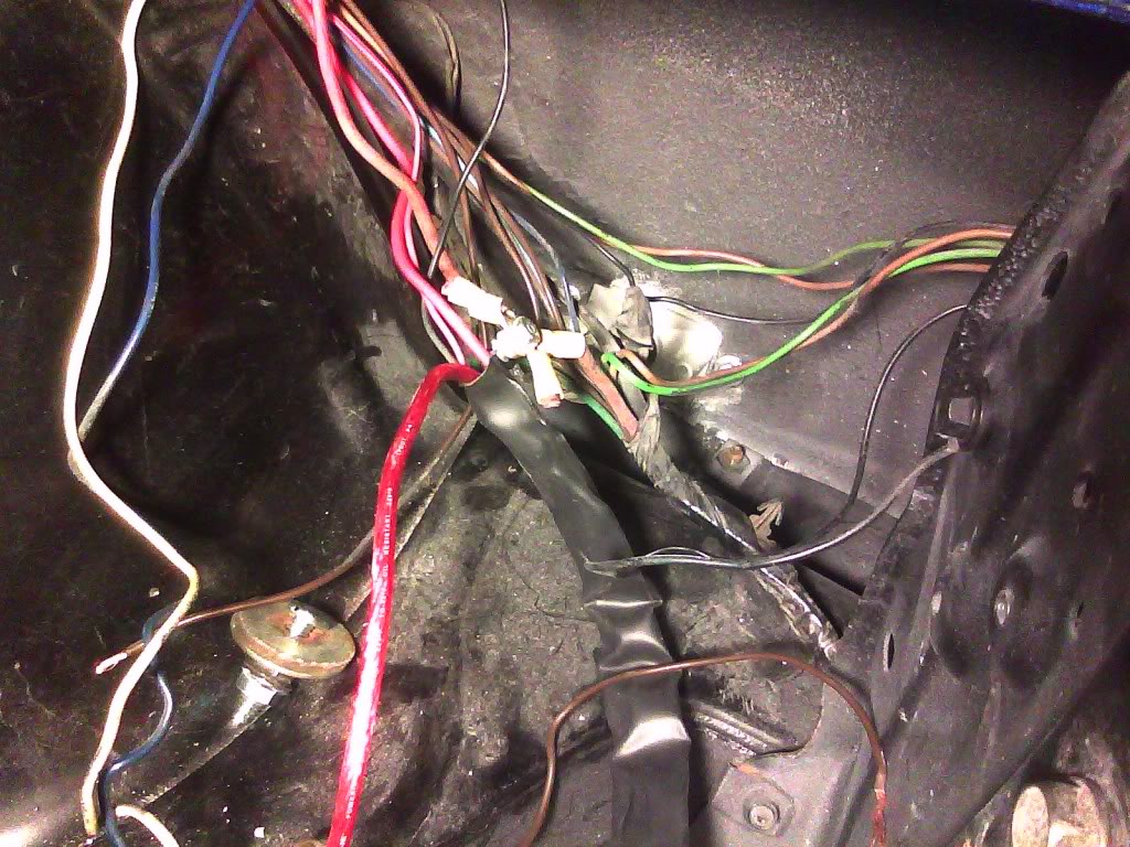
Yeah, everybody should do their wiring this way. Keeps the tape industry in business.
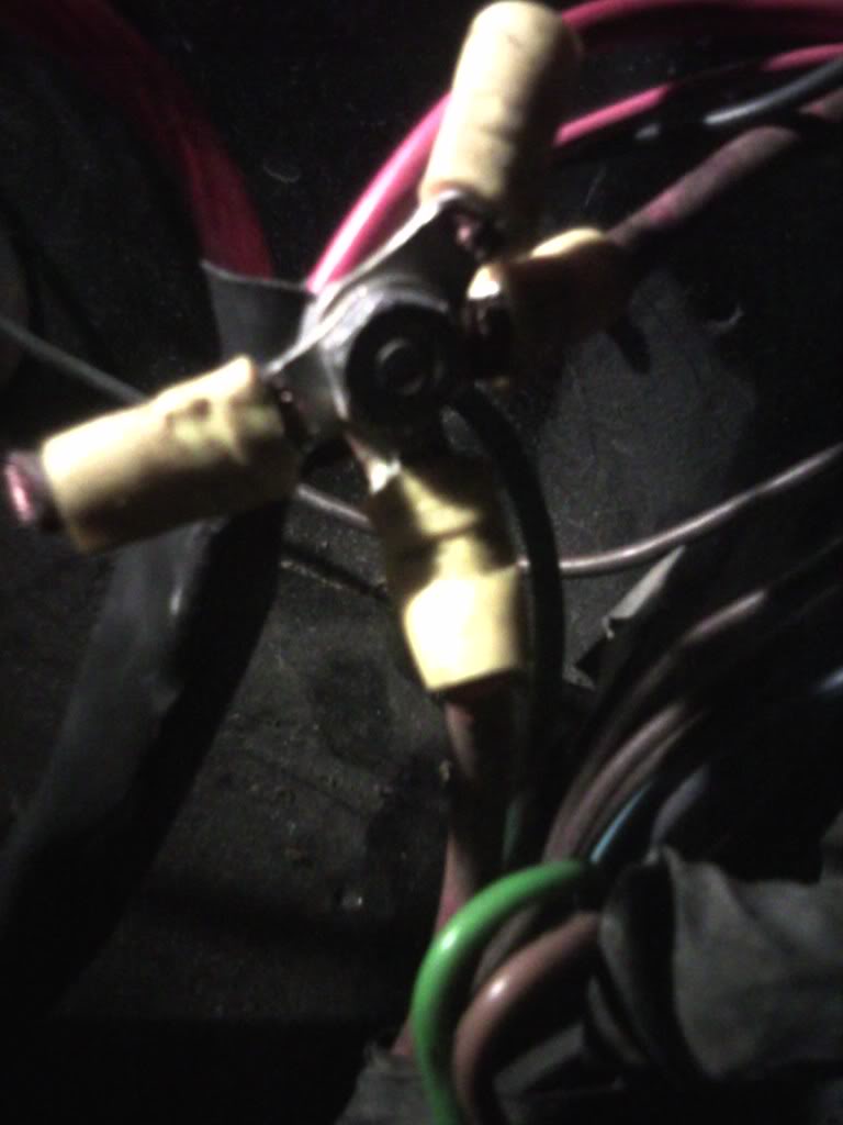
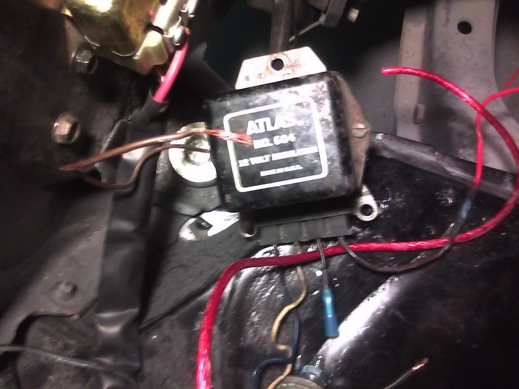
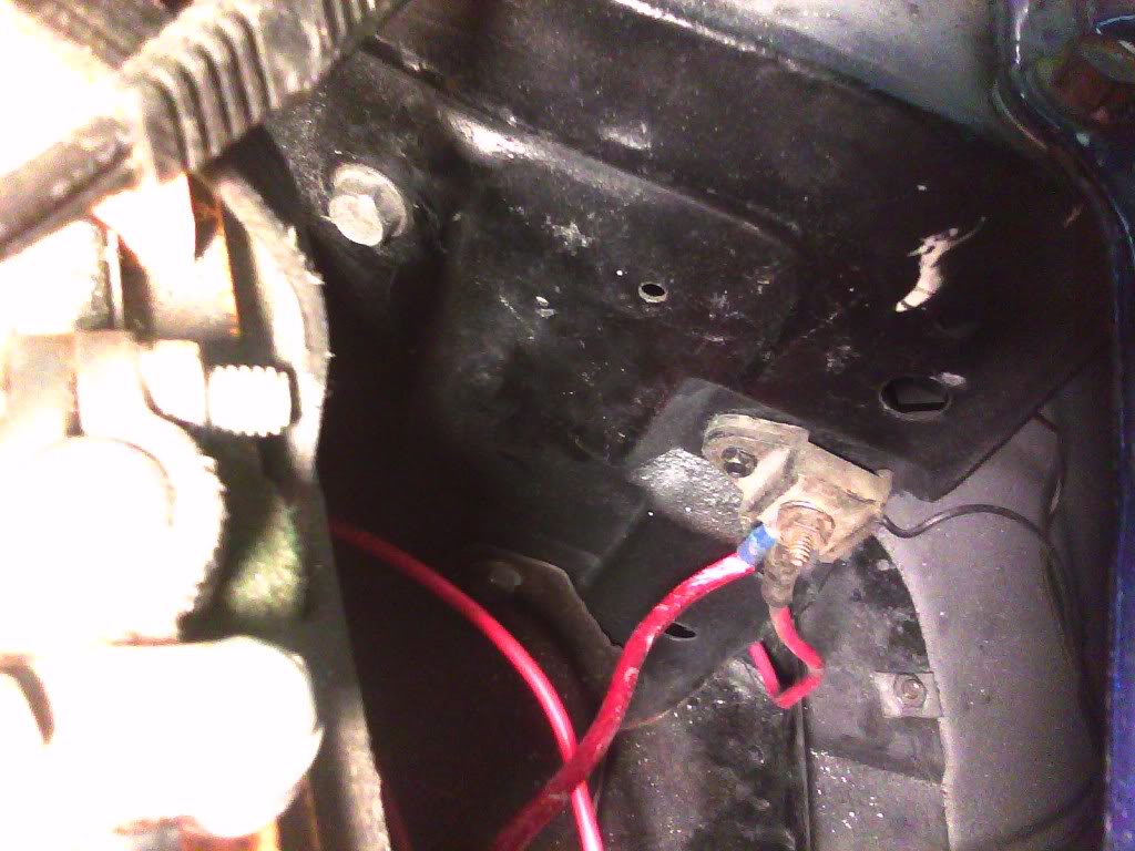
This is the junction box just behind the battery
Here is the VR. They had a diode twisted and spliced into the 2nd wire that now has a butt connector.
Surprise!
Yeah, everybody should do their wiring this way. Keeps the tape industry in business.
This is the junction box just behind the battery
Last edited by StoveBolts; 01-25-2011 at 07:32 AM.